Material Evolution File
How Carbon Fiber Became Structural
Trace how carbonized threads became engineered fibers, scalable composites, and specialized materials with tightly controlled properties.
Early carbonized fiber
Lamp Filaments Before Structural Fiber
Selected file: Lamp Filaments Before Structural Fiber. Choose another file to update this evidence card.
Starting material
Thomas Edison tested carbonized cotton thread and later bamboo for incandescent-lamp filaments in the late 1870s. Pyrolysis preserved a slender carbon shape that could conduct electricity and glow.
Designed function
These filaments were selected for electrical resistance and service inside a lamp, not for carrying structural loads. Their existence did not yet provide a high-strength reinforcement material.
What the method established
An organic fiber could be converted into a mostly carbon fiber without losing its overall form. Later work would control orientation, defects, purity, and continuous processing.
Carbonization was demonstrated early, but useful structural performance still depended on controlling the carbon at much smaller scales.
Laboratory property record
Roger Bacon’s Graphite Whiskers
Selected file: Roger Bacon’s Graphite Whiskers. Choose another file to update this evidence card.
1958 observation
At Union Carbide’s Parma laboratory, Roger Bacon found long graphite whiskers in carbon-arc deposits. Their highly ordered structure displayed exceptional tensile strength and stiffness for their mass.
Atomic arrangement
The whiskers contained graphitic sheets oriented along the filament. Strong carbon bonds carried axial tension, while the filament form reduced the chance that a large flaw would start failure.
Scale barrier
The arc process produced costly laboratory specimens rather than continuous yarn. It proved the attainable properties of oriented carbon but did not provide a practical manufacturing route.
The experiment shifted the target from merely making carbon threads to reproducing ordered, low-defect carbon in continuous fiber.
Cellulose process record
Rayon Enters Advanced Composites
Selected file: Rayon Enters Advanced Composites. Choose another file to update this evidence card.
Continuous feedstock
Rayon supplied uniform yarns that could pass through furnaces as cloth or tow. Carbonized rayon reached commercial production in 1959, first serving thermal and aerospace uses.
Hot stretching
In 1964, Roger Bacon and Wesley Schalamon stretched rayon-derived yarn while heating it above 2,800 degrees Celsius. The treatment oriented carbon layers nearer the fiber axis and sharply raised modulus.
Remaining limitation
Rayon loses much of its mass during conversion and required demanding high-temperature treatment. It opened the commercial path, but PAN later offered stronger fibers and better process economics.
Rayon connected laboratory carbon structures to continuous yarn, then revealed why precursor chemistry controls yield and final performance.
Dominant precursor route
PAN Makes High Strength Scalable
Selected file: PAN Makes High Strength Scalable. Choose another file to update this evidence card.
Japanese development
Akio Shindo reported high-performance fibers made from polyacrylonitrile around 1959–1961. PAN’s oriented polymer backbone could be stabilized and carbonized while retaining a useful fibrous structure.
British process
William Watt and colleagues at Britain’s Royal Aircraft Establishment developed another high-performance PAN route in the early 1960s. Industrial licensing helped move the material into production.
Controlled conversion
PAN tow is oxidatively stabilized so it will not melt, then heated without oxygen to remove non-carbon atoms. Tension and furnace conditions preserve axial orientation and limit damaging defects.
Market outcome
PAN became the main precursor for high-strength commercial carbon fiber. Its balance of tensile strength, modulus, process control, and continuous output displaced rayon in most structural applications.
PAN converted high performance from a scarce specimen into repeatable tow suited to aircraft, pressure vessels, sporting goods, and industry.
Property specialization record
Mesophase Pitch Extends the Range
Selected file: Mesophase Pitch Extends the Range. Choose another file to update this evidence card.
Liquid-crystal precursor
Leonard Singer’s 1970 work at Union Carbide used mesophase pitch, whose ordered liquid-crystalline regions could be spun and graphitized with strong axial alignment.
Distinct property profile
Mesophase-pitch fibers can reach very high modulus and thermal conductivity. Many grades, however, have lower tensile or compressive strength than high-strength PAN fibers and demand careful handling.
Application fit
The pitch route serves stiffness- and heat-transfer-led designs such as space structures, thermal-management components, and some friction products rather than replacing PAN across every use.
Pitch showed that carbon fiber is a tunable material family: the best precursor depends on the load, temperature, and heat-flow requirement.
Composite design record
Fiber Becomes a Load-Bearing Part
Selected file: Fiber Becomes a Load-Bearing Part. Choose another file to update this evidence card.
Shared work
Carbon filaments carry most tensile load along their length. A polymer matrix fixes their position, transfers shear between them, protects the surface, and gives the part its shape.
Directional design
Unidirectional plies are strong and stiff mainly along the fiber axis. Engineers stack selected angles so a laminate can resist the actual tension, compression, shear, and torsion expected in service.
Interface control
Surface treatment and a thin sizing coating help fibers bond with the chosen resin and survive handling. Weak adhesion wastes fiber capacity; excessive surface damage can reduce fiber strength.
Production choices
Prepreg layup, resin infusion, compression molding, filament winding, pultrusion, and automated placement suit different shapes, volumes, tolerances, and certification demands.
The visible weave is not the material’s whole story; ply direction, resin, interface, cure, and defects determine the finished part.
End-of-life research record
Recovering Fiber Without Losing Value
Selected file: Recovering Fiber Without Losing Value. Choose another file to update this evidence card.
Thermoset obstacle
Most structural epoxy matrices form permanent crosslinked networks. They cannot simply be melted away, and separating valuable fibers from cured resin is harder than remelting a metal.
Available routes
Mechanical grinding produces short filler; pyrolysis removes resin with heat; solvolysis uses chemical media to break matrix bonds. Each route changes fiber length, surface condition, cost, or energy demand.
Design question
Recovered discontinuous fiber can serve molded compounds, nonwoven mats, and other secondary products. Returning it to certified continuous-fiber structures remains much more difficult.
Current research
Recent chemical-recycling studies aim to recover both clean fiber and useful resin-derived molecules. Laboratory success still requires collection systems, repeatable feedstock, scale, and qualified markets.
The next material advance is not only stronger fiber; it is retaining more of the fiber’s value through repair, reuse, and recovery.
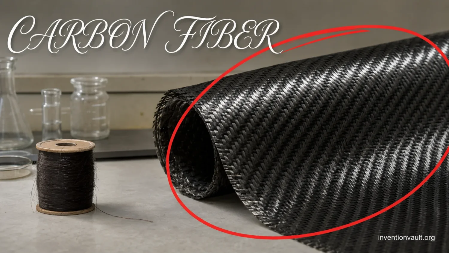
Carbon fiber is a family of thin, carbon-rich filaments engineered for high tensile strength and stiffness at low mass. Its modern structural form was not invented in one event. Nineteenth-century lamp makers carbonized organic threads, 1950s researchers demonstrated the potential of highly ordered graphite whiskers, and teams in Japan, Britain, and the United States developed continuous rayon-, PAN-, and pitch-based production routes. The familiar black material in an aircraft panel or bicycle frame is usually not bare fiber but carbon-fiber-reinforced polymer, or CFRP, in which aligned fibers work with a resin matrix.
Material Definition
Carbon fiber is the reinforcement filament or tow. CFRP is the finished composite of carbon fiber and a polymer matrix. Their properties and manufacturing histories overlap, but they are not interchangeable terms.
| Material record | What it established | Main limitation or role |
|---|---|---|
| Carbonized cotton and bamboo, late 1870s | Organic filaments could retain their form after carbonization | Designed as electrical lamp filaments, not structural reinforcement |
| Roger Bacon’s graphite whiskers, 1958 | Highly oriented carbon could deliver exceptional strength and stiffness by weight | Laboratory method was not suited to continuous low-cost yarn |
| Commercial rayon-derived fiber, 1959 onward | Continuous carbon cloth and tow entered thermal and aerospace service | Low yield and demanding heat treatment restricted the route |
| PAN-derived fiber, developed around 1959–1964 | Repeatable high strength and scalable continuous processing | Stabilization remains slow and energy intensive |
| Mesophase-pitch fiber, 1970 onward | Very high modulus and thermal conductivity became attainable | Suited to specialized property targets rather than every structural load |
Why Carbon Fiber Is Light and Strong
A carbon fiber is typically only several micrometers in diameter. Inside it, carbon atoms form small, sheet-like regions with strong covalent bonding. Processing orients many of these regions roughly parallel to the fiber axis. A tensile load applied in that direction can therefore use the strong carbon-carbon bonds efficiently.
The fiber form matters as much as the chemistry. Large pieces of brittle material contain more opportunities for a crack-starting flaw. Dividing the reinforcement into thousands of fine filaments limits the size of many individual defects. A tow gathers those filaments into a manageable bundle; a label such as 12K means that the tow contains about 12,000 filaments.
Low density gives carbon fiber its often-quoted specific strength and specific stiffness. Those are strength or stiffness divided by density, which are more useful than raw strength alone when mass must be minimized. Commercial grades vary widely, and no single number describes the family. PAN-based high-strength fibers, PAN high-modulus fibers, and pitch-based high-modulus fibers occupy different parts of the property range.
Carbon fiber is not equally strong in every direction. It is also relatively brittle and reaches failure at low strain compared with ductile metals. A composite can be highly resistant to repeated axial loading yet remain vulnerable to impact damage, delamination, poor joints, or loads applied across the plies. “Stronger than steel” is therefore incomplete unless the comparison states the grade, direction, test, part geometry, and mass basis.
From Lamp Filament to Engineered Reinforcement
Carbonized Threads Came First
Early incandescent lamps needed a slender conductor that could glow at high temperature. Edison and other lamp developers tested carbonized plant fibers and threads because pyrolysis left a carbon shape with useful electrical resistance. These filaments were commercially important, but their purpose and performance were far removed from a modern aircraft-grade reinforcement.
Rayon revived the idea in the mid-twentieth century. It arrived as a consistent, spinnable cellulose fiber that could be woven before conversion. Carbonized rayon cloth found uses in high-temperature insulation and ablative structures, where heat resistance mattered even before the material attained high structural modulus.
1958 Revealed the Mechanical Potential
Roger Bacon’s carbon-arc work at Union Carbide produced graphite whiskers with far better mechanical properties than the commercial carbon fibers of the period. The ordered sheets ran along the filaments, offering experimental evidence that a carbon fiber could be both light and extraordinarily stiff. The process itself was too costly and discontinuous for structural production, so the result defined a target rather than a factory method.
Dating the First
An early carbonized lamp filament, a high-performance graphite whisker, a continuous structural yarn, and a commercial PAN fiber answer different “first” questions. Assigning one inventor without stating the definition erases the actual development path.
Three Precursor Routes Defined the Industry
Rayon provided the earliest commercial structural route. In the 1960s, hot stretching at very high temperature improved alignment and modulus, leading to Union Carbide’s Thornel yarns. Yet cellulose gives a relatively low carbon yield and shrinks heavily during conversion. Those losses made it difficult to compete with PAN for broad structural use.
Akio Shindo’s work in Japan showed that polyacrylonitrile could yield high-performance fiber, while William Watt’s team at the Royal Aircraft Establishment established a related British route. PAN could be spun with molecular orientation, stabilized so the fiber would not melt, and carbonized while much of that alignment was retained. Commercial agreements and continued chemistry work turned PAN into the leading precursor for high-strength products.
Mesophase pitch created a separate branch. Leonard Singer recognized that ordered liquid-crystalline regions in selected pitch could be spun into a precursor whose carbon layers aligned very well after graphitization. The resulting fibers can deliver extremely high axial modulus and high thermal conductivity. PAN remains the usual choice where tensile and compressive strength need a better balance; pitch is selected when stiffness, dimensional stability, or heat flow dominates.
How PAN-Based Carbon Fiber Is Made
The production line must transform an organic polymer into carbon without allowing the fine filaments to fuse, melt, or accumulate performance-limiting flaws. Temperature, atmosphere, residence time, and tension are controlled continuously across thousands of filaments.
- Polymer and spin the precursorA PAN copolymer is dissolved and extruded through spinneret holes. Drawing aligns the polymer chains, while washing and drying produce continuous precursor tow.
- Stabilize in airControlled heating, commonly in the low hundreds of degrees Celsius, converts the linear PAN chemistry into a heat-stable ladder-like structure. Tension limits shrinkage and preserves orientation.
- Carbonize without oxygenThe stabilized tow passes through inert-atmosphere furnaces at roughly 1,000–1,500 degrees Celsius. Hydrogen, nitrogen, and oxygen leave in gaseous products as carbon-rich, oriented structures develop.
- Raise modulus when requiredSome grades receive higher-temperature treatment to increase carbon-layer order and stiffness. The chosen schedule can trade strain capability and strength for greater modulus.
- Treat the surfaceA controlled oxidation step adds chemically active sites so the otherwise low-reactivity carbon surface can transfer load more effectively to a resin.
- Apply sizing and packageA thin, resin-compatible coating protects filaments during handling and aids interfacial bonding. The tow is then wound for weaving, prepregging, winding, pultrusion, or direct placement.
Stabilization is one of the slowest stages because oxygen must diffuse through the filament while heat from the reaction is controlled. Heating too rapidly can create an uneven skin-core structure or damage the tow. Research has examined plasma oxidation, alternative precursors, faster heating, and other routes to reduce energy use and production time without sacrificing uniformity.
Furnace treatment alone does not guarantee a strong composite. Carbonization can leave a relatively inert surface. Manufacturers therefore adjust surface chemistry and add sizing for a particular matrix family. The interface must transfer shear without becoming so weak that fibers pull out too early or so aggressive that treatment damages the filaments.
Fiber, Resin, and Ply Direction Work Together
Bare carbon fiber is rarely used as a free-standing structural material. The matrix holds fibers in alignment, spreads local loads, protects them from abrasion, and resists loads across the fiber direction. Epoxy is common in demanding thermoset composites, while polyester, vinyl ester, and heat-resistant resins serve other environments. Thermoplastic matrices offer fast forming, toughness, weldability, and different recovery options, but they can require higher processing temperatures or pressures.
A unidirectional ply puts nearly all fibers in one direction. Woven cloth interlaces yarns for handling and multidirectional reinforcement, though the crimp can reduce the straight-fiber efficiency. Designers combine 0-degree, 90-degree, and angled plies according to the load path. The stacking sequence also affects bending, twisting, thermal movement, damage tolerance, and the tendency for layers to separate.
| Form or process | How material is placed | Typical reason for selection |
|---|---|---|
| Prepreg and autoclave | Fiber arrives pre-impregnated with controlled resin; heat and pressure consolidate the layup | Low void content, close material control, and demanding aerospace parts |
| Resin infusion or RTM | Dry reinforcement is placed in a mold before liquid resin is drawn or injected through it | Larger parts, closed molds, and less reliance on refrigerated prepreg |
| Filament winding | Continuous tow is wound along programmed paths over a rotating mandrel | Pipes, tanks, rocket motor cases, and pressure vessels |
| Pultrusion | Continuous fibers are pulled through resin and a heated shaping die | Long profiles with a constant cross-section |
| Compression molding | Sheet, chopped charge, or tailored preform is pressed and cured in matched tooling | Shorter cycles and repeated production of shaped parts |
| Automated fiber placement | Robotic heads lay narrow prepreg tows along calculated paths | Large integrated structures with controlled orientation and less manual layup |
Manufacturing defects can defeat an excellent fiber. Voids interrupt load transfer; wrinkles bend fibers away from the intended direction; resin-rich areas add mass without matching reinforcement; poor cure changes matrix properties; and drilled holes can introduce delamination. Inspection, process records, and repair procedures are therefore part of the material system rather than afterthoughts.
Where Lightweight Strength Changes the Design
Aircraft and Spacecraft
Aerospace structures gain value when mass saved in one component reduces fuel, payload penalties, or the size of supporting systems. CFRP can also combine skin and stiffening functions in large molded parts and resists corrosion in many environments. Qualification is demanding because impact damage may be hidden beneath the surface, joints interrupt continuous fibers, and repair must restore a known load path.
Pressure Vessels and Rotating Equipment
Filament winding places continuous fibers around a vessel in directions that resist hoop and axial stresses. This makes carbon composite overwrapped pressure vessels useful where stored gas and low mass must coexist. High-speed rollers, robot arms, and shafts use stiffness at low rotational inertia to move faster or maintain shape with less drive load.
Wind Energy, Transport, and Civil Repair
Selected wind-turbine blade designs use carbon reinforcement in spar caps, where axial stiffness can control blade deflection. Automotive adoption concentrates where weight saving, production rate, crash behavior, and cost can be reconciled. In construction, carbon-fiber sheets, plates, and tendons can strengthen existing concrete or masonry with little added thickness, but anchorage, fire protection, surface preparation, and engineering assessment remain essential.
Sport, Medical Imaging, and Precision Products
Bicycle frames, rackets, fishing rods, golf shafts, paddles, and prosthetic components use directional layups to tune stiffness, flex, and mass. Carbon composites also transmit X-rays more readily than many metals, which supports radiolucent patient tables and imaging components. These applications still depend on the whole laminate, not the visible weave or a generic “carbon” label.
Limits That Metals Often Handle Better
Carbon composites do not yield and bend like many metals before failure. Damage may appear as matrix cracking, fiber breakage, crushing, or delamination, sometimes with little surface evidence. Fasteners create stress concentrations, while bonded joints need controlled surfaces and cure conditions. Specialized inspection methods may be required after impact.
The fibers conduct electricity. Contact between carbon composite and aluminum in a wet, salty environment can promote galvanic corrosion of the aluminum unless the materials are isolated and the joint is designed accordingly. Electrical conductivity also changes lightning-strike protection, electromagnetic behavior, and workshop controls.
Service temperature often depends more on the matrix than on the carbon reinforcement. An epoxy can soften, degrade, or burn long before the fibers lose their carbon structure. Moisture, ultraviolet exposure, fire, chemical contact, and thermal cycling must therefore be evaluated for the selected resin and laminate rather than assigned to carbon fiber in general.
Machining Dust
Cutting, drilling, or sanding CFRP can release irritating fibers and resin-bearing dust, while conductive particles can damage electrical equipment. Industrial work requires process-specific extraction, housekeeping, protective equipment, and the material supplier’s safety data.
Cost, Energy, and the Recycling Problem
Carbon fiber begins with a carefully prepared precursor and passes slowly through controlled thermal stages. Yield loss, energy use, quality control, and the need to protect thousands of filaments all raise cost before a part is molded. Composite fabrication can then add tooling, refrigerated prepreg storage, manual layup, autoclave time, trimming, inspection, and certification.
High-volume processes aim to shorten this chain through larger tows, faster stabilization, out-of-autoclave curing, resin transfer, thermoplastic forming, compression molding, and automated placement. Each method has tradeoffs in fiber straightness, wet-out, voids, surface finish, scrap, cycle time, and achievable geometry. A cheaper fiber does not automatically create a cheaper qualified part.
End-of-life handling is harder when continuous carbon fibers are locked inside a crosslinked resin. Grinding is simple but reduces the material to short reinforcement or filler. Pyrolysis can free the fibers by decomposing resin, though heat may alter surface condition and the resin is not recovered as its original network. Solvolysis can separate constituents more selectively, but chemical recovery, feedstock variability, and industrial scale remain obstacles.
Research published in 2025 and 2026 has reported chemical routes that preserve useful fiber while recovering resin-derived compounds. These are promising process results, not proof that every existing CFRP item can enter a closed commercial loop. Product design, traceable resin chemistry, collection, cleaning, certification, and demand for recovered material must develop with the separation process.
What Carbon Fiber Actually Changed
Carbon fiber gave engineers a reinforcement whose direction could be matched to a load with far less mass than a comparable isotropic metal design in suitable applications. It also changed manufacturing logic: material and part are created together as fibers are placed, resin is introduced, and the laminate is cured. Geometry, orientation, interface chemistry, and processing history become inseparable from the finished properties.
Its history is therefore best understood as a series of solved constraints. Carbonized threads proved shape retention. Graphite whiskers exposed the property ceiling. Rayon enabled continuous early products. PAN delivered scalable strength, while mesophase pitch opened very high stiffness and thermal conductivity. Composite design turned those filaments into usable structures. Current work is directed at faster production, lower-impact precursors, tougher matrices, repair, and recovery that retains more of the energy and precision already invested in the fiber.
Questions People Ask About Carbon Fiber
Who invented carbon fiber?
No single name covers every meaning of the term. Edison used carbonized organic filaments in lamps; Roger Bacon demonstrated high-performance graphite whiskers in 1958; Akio Shindo and William Watt developed influential PAN routes; Bacon and Wesley Schalamon improved rayon-derived high-modulus yarn; and Leonard Singer developed mesophase-pitch fiber.
Is carbon fiber stronger than steel?
Some carbon fibers have far higher tensile strength per unit mass than common steels, especially along the fiber direction. A steel part may still perform better under impact, bearing, transverse load, high-temperature exposure, or ductile deformation. The correct comparison is between complete parts designed for the same service.
Why is most carbon fiber black?
The carbon-rich filaments absorb visible light and appear black. Colored carbon-look products may use dyed glass or other fibers, while a CFRP surface can receive paint or a tinted clear coat without changing the underlying filament color.
Can carbon fiber rust?
It does not rust like iron, but the matrix and interface can degrade under unsuitable heat, moisture, chemicals, or ultraviolet exposure. Its electrical nobility can also accelerate corrosion of a contacting metal such as aluminum when an electrolyte is present.
Can carbon-fiber composites be recycled?
Yes, but the output is not always equivalent to virgin continuous fiber. Mechanical, thermal, and chemical routes can recover material at different quality levels. The main challenge is preserving length and surface performance while separating mixed matrices at workable cost and scale.
References Used for This Article
- American Chemical Society, “High Performance Carbon Fibers” — used for the Edison, Bacon, rayon, PAN, and mesophase-pitch development record.
- U.S. Department of Energy, “Plasma Oxidation of Carbon Fiber Precursor” — used for PAN stabilization, production bottlenecks, and faster oxidation research.
- Oak Ridge National Laboratory, “Designing the Structure of Carbon Fibers for Optimal Mechanical Properties” — used for precursor-dependent microstructure and defect control.
- Akio Shindo, “Structure and Properties of Carbon Fiber Surface” — used for surface treatment, active sites, and fiber-resin adhesion.
- National Renewable Energy Laboratory, 2025 composite recycling report — used for recent chemical recovery of fibers and resin-derived products.
- RSC Applied Polymers, review of reuse, recovery, and recycling of thermoset composites — used for the comparison of mechanical, thermal, and chemical routes.
- Monash University, carbon-fibre-composite safety information — used for machining dust, resin exposure, and electrical housekeeping limits.