
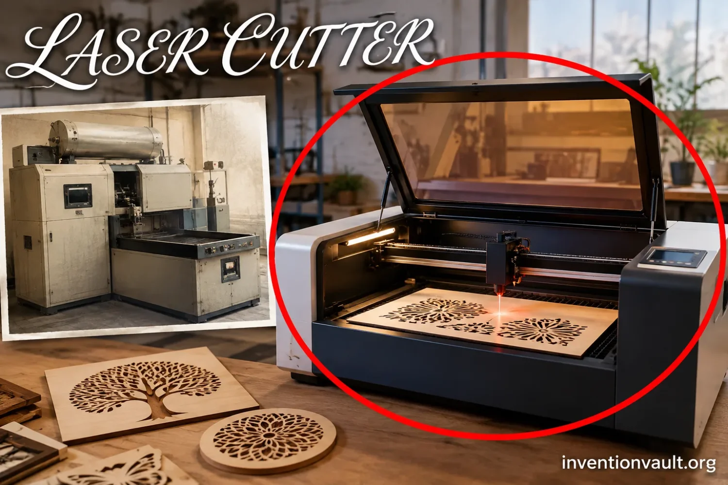
Claims and Process Milestones
How Laser Cutting Took Shape
Follow the shift from the first working lasers to production machining, oxygen-assisted steel cutting, numerical control, and modern fiber systems.
Laser source milestone
The Working Ruby Laser
Current stage
Demonstration
Theodore Maiman and Irnee D’Haenes demonstrated a working ruby laser at Hughes Aircraft in May 1960. Its output came as pulses rather than a continuous beam.
What existed
Engineers now had a concentrated optical energy source that could be focused onto a very small area. That did not yet amount to a laser cutting process.
Missing machinery
A usable cutter still needed a suitable laser source, focusing optics, a way to remove material from the cut, and controlled movement between beam and workpiece.
The laser supplied the energy source; turning that light into a controllable manufacturing tool required several more engineering steps.
Industrial laser milestone
The CO2 Laser Arrives
Current stage
Developer
C. Kumar N. Patel demonstrated lasing from carbon dioxide at Bell Laboratories in 1964, opening a route to gas lasers suited to much higher continuous output than the first ruby device.
Rapid scale-up
Within only a few years, a 300 W slow-flow CO2 laser was operating at the Services Electronic Research Laboratory in Britain and became available for cutting trials.
Manufacturing value
CO2 systems could deliver sustained optical energy to a focused spot, making them well suited to experiments that required a beam to travel continuously along a cut path.
A more suitable industrial light source made continuous thermal cutting a realistic engineering problem rather than only a laboratory possibility.
Production milestone
Laser Machining Diamond Dies
Current stage
Production problem
Fine copper wire was drawn through hard diamond dies. Forming the initial opening in a diamond was laborious because the material resisted ordinary machining methods.
Western Electric
In 1965, Western Electric’s Engineering Research Center applied a ruby laser to make holes in diamond wire-drawing dies used in production.
Definition issue
The operation pierced and shaped a hole rather than tracing a contour through sheet metal, so it also fits the modern description of laser drilling or laser machining.
The 1965 system established laser material removal in production, but it was not yet the gas-assisted profile-cutting process familiar today.
Process design milestone
Houldcroft’s Cutting Nozzle
Current stage
Design idea
Peter Houldcroft proposed combining a focused CO2 laser with an oxygen jet after considering the limits of plasma trimming for prototype vehicle body panels.
Coaxial flow
His 1967 nozzle placed an oxygen pressure chamber around the optical path so the reactive gas emerged around the focused beam at the cutting point.
Early geometry
TWI records a nozzle orifice of about 2.5 mm and a stand-off distance of roughly 1.5 mm, dimensions surprisingly close in concept to later cutting heads.
The nozzle joined optical heating and controlled gas flow into one cutting head, creating the process architecture that endured.
Cutting experiment
Gas-Assisted Steel Cutting
Current stage
First trials
In May 1967, a focused 300 W slow-flow CO2 laser and oxygen assist gas were used to cut 1 mm steel sheet during experiments associated with TWI and SERL.
Researchers
Houldcroft devised the cutting approach and nozzle. Arthur B. J. Sullivan of SERL operated the laser and later co-authored the published account of the experiments.
Measured performance
Later trials cut high-carbon tool steel and stainless steel up to 2.5 mm thick at speeds reaching about 1 m/min, with a reported focused spot near 0.4 mm.
Beam, focus, oxygen jet and moving workpiece were now functioning together as a recognizable metal-cutting process.
Machine-tool milestone
Cutting Follows Programmed Paths
Current stage
Boeing research
A 1969 Boeing paper examined oxygen-assisted CO2 cutting of difficult materials including titanium, Hastelloy and ceramics while considering what a practical laser machine tool might become.
Numerical control
Messer records that its predecessor CRO Engineering delivered an American-built numerically controlled laser cutting machine for aerospace titanium shape cutting in 1969.
Shape control
Numerical control allowed the cutting path to become programmable. The laser no longer needed to perform one fixed piercing task or depend on manually guided specimen movement.
Programmable motion turned a cutting process into a versatile machine tool able to reproduce different contours from controlled coordinates.
Modern machine architecture
CO2, Fiber and CNC Cutting
Current stage
Machine control
Modern cutters coordinate the laser, optics, assist gas and motion through CNC systems that follow programmed paths rather than relying on the experimental positioning methods of the 1960s.
Laser families
CO2 lasers remain useful for many materials, while fiber lasers use a solid gain medium and have become especially well suited to metal cutting and reflective metals.
Persistent principle
The cutting head still concentrates optical energy at the workpiece and commonly delivers gas through the same region to remove molten material or assist the reaction.
Laser sources and controls changed greatly, while the focused beam, nozzle, assist gas and controlled motion remain recognizable descendants of the early process.
The laser cutter does not have one uncontested inventor or one date that describes every stage of its creation. Western Electric used a ruby laser to machine diamond wire-drawing dies in production in 1965, a milestone often described as the first production laser cutting machine. A process much closer to modern laser cutting appeared in May 1967, when Peter Houldcroft’s idea for an oxygen-assisted cutting nozzle was tested with Arthur B. J. Sullivan and a 300 W CO2 laser, producing cuts in steel. The distinction matters because drilling a hole in diamond and continuously cutting a metal contour are different manufacturing operations.
| Laser Cutter Invention Record | Historical Detail |
|---|---|
| Early production laser-machining milestone | 1965, Western Electric Engineering Research Center |
| Early production task | Piercing diamond wire-drawing dies with a ruby laser |
| Gas-assisted metal-cutting milestone | May 1967 |
| Process originator | Peter Houldcroft, The Welding Institute |
| Experimental collaborator | Arthur B. J. Sullivan, Services Electronic Research Laboratory |
| 1967 laser | 300 W slow-flow CO2 laser |
| Assist gas | Oxygen |
| Published account | Gas-jet laser cutting, August 1967 |
| Process inherited by later machines | Focused beam + cutting nozzle + assist gas + controlled motion |
Why 1965 and 1967 Are Both Given as the Invention Date
The wording “invention of the laser cutter” combines several events that did not happen at the same time. A laser first had to become capable of removing material. Then engineers had to make that useful on a factory task. Continuous profile cutting required another step: the beam had to work with a gas jet so molten or reacting material could leave a narrow cutting channel while the beam or workpiece moved.
Dating the First Laser Cutter
1965 is commonly used for Western Electric’s production laser system for diamond-die holes. 1967 is the stronger date for the emergence of gas-assisted metal laser cutting in a form directly related to present industrial cutters.
Calling both events “laser cutting” is understandable, but it can hide the engineering difference. The Western Electric machine removed diamond to create an opening. The later British work established a moving cut through sheet material with a focused CO2 beam and coaxial oxygen flow.
The Laser Had to Come First
The cutter’s history begins only a few years after the invention of the laser itself. Theodore Maiman and Irnee D’Haenes demonstrated a working ruby laser at Hughes Aircraft in May 1960. The Smithsonian’s surviving spectrometer plate from those experiments records the pulsed ruby-laser work.
That achievement supplied concentrated coherent light, but it did not automatically create a manufacturing machine. A usable cutting system still needed enough optical output for the material, focusing optics, a controllable interaction with the workpiece and some way to remove material from the developing cut.
The CO2 Laser Opened a Better Route to Continuous Cutting
C. Kumar N. Patel’s demonstration of carbon-dioxide laser action at Bell Laboratories in 1964 changed the available engineering options. CO2 lasers could be developed to much higher continuous output than the first ruby systems. Only a few years later, a 300 W slow-flow CO2 laser was operating at the Services Electronic Research Laboratory, usually abbreviated SERL, in Harlow, England.
That machine was far removed from a compact shop-floor cutter. TWI’s historical record describes five discharge sections extending to a total laser length of about 10 meters. Yet the device could provide the optical output needed for a new kind of experiment: moving a concentrated heat source through metal rather than firing isolated pulses into a tiny target.
1965: Western Electric Puts Laser Machining Into Production
One of the earliest useful factory problems for laser machining involved an exceptionally hard material: diamond. Fine copper wire was produced by pulling progressively smaller wire through precision dies. Diamond was suited to the final dies because it resisted wear, but that same hardness made forming the initial opening difficult.
Morris Tanenbaum, who led Western Electric’s Engineering Research Center, later described how laborious the first hole in a diamond die had been. The laser offered something conventional tooling could not easily provide: energy concentrated onto a very small area without requiring a cutting edge harder than the diamond itself.
In 1965, Western Electric applied a ruby laser to the diamond-die problem at its production operation. Historical summaries commonly identify the equipment as the first production laser cutting machine. The more technically careful description is an early production laser-machining or laser-drilling system, because the beam was piercing and enlarging a hole rather than tracing a long separation cut through sheet.
Why the Diamond-Die Application Mattered
The importance of the Western Electric system was not that it already resembled a modern gantry laser cutter. It showed that a laser could leave the optics laboratory and solve a repetitive manufacturing problem on a material that was troublesome to machine mechanically.
It also exposed an idea that would remain central to laser manufacturing: the tool itself did not need a physical edge touching the work. The concentrated beam delivered energy remotely, so there was no conventional blade or drill point wearing against the diamond.
That was enough to establish laser material processing as useful production technology. It was not enough to solve profile cutting.
The Manufacturing Problem That Led to Gas-Assisted Cutting
Peter Houldcroft’s route to laser cutting began with a different problem. According to TWI’s account, Houldcroft visited the British Motor Corporation in 1965 and saw work on trimming prototype body panels with a plasma torch carried by an articulated arm. The arrangement did not provide the required accuracy and could produce burning around the work.
The question was whether another thermal process could make the cut more precisely. During the journey back to Cambridge, Houldcroft began considering a combination of a tightly focused laser beam and an oxygen jet.
The idea contained two separate functions. The beam would deliver concentrated heat exactly where the cut was wanted. The gas stream could assist the thermal reaction and help remove material from the developing slot. Availability of the 300 W CO2 laser at SERL made the concept testable.
1967: The Cutting Nozzle Joins Beam and Oxygen
Houldcroft designed a laser cutting nozzle in early 1967. The arrangement was more than a tube pointed near a laser spot. The beam passed through a focusing system and an oxygen pressure chamber so that the assist gas emerged coaxially around the region of the laser focus.
TWI’s surviving description gives unusually detailed dimensions for this early cutting head. The nozzle tip had a circular opening of about 2.5 mm and operated at a stand-off distance of about 1.5 mm from the workpiece. A focusing lens sat above the pressure chamber. The horizontal beam from the large CO2 laser was redirected downward using a mirror.
The lens and pressure window in the experimental apparatus were made from sodium chloride, an optical material capable of transmitting the CO2 laser wavelength. Later industrial cutting heads would use different materials, refined optics, tighter control and far more compact equipment, but the arrangement of beam, focus, nozzle, gas and workpiece was already recognizable.
May 1967: The Gas-Assisted Laser Cuts Steel
The first gas-assisted trials took place in May 1967. A 300 W slow-flow CO2 laser supplied the beam, while Houldcroft’s nozzle delivered oxygen into the cutting zone. The first experiments included cutting 1 mm steel sheet.
Arthur B. J. Sullivan worked at SERL and operated the laser during the experiments. Sullivan and Houldcroft later published the results in the August 1967 issue of the British Welding Journal under the title Gas-jet laser cutting.
The later experimental results went beyond the first thin sheet. TWI’s archival account reports cuts in high-carbon tool steel and stainless steel up to 2.5 mm thick, with cutting speeds reaching about 1 meter per minute. A focused spot diameter of about 0.4 mm was reported, and the preferred focal position for the tested materials was near the surface of the workpiece.
| 1967 Experimental Feature | Recorded Detail |
|---|---|
| Laser type | Slow-flow CO2 laser |
| Maximum optical output used for the work | 300 W |
| First reported sheet-cutting demonstration | 1 mm steel |
| Assist gas | Oxygen |
| Nozzle opening | About 2.5 mm |
| Stand-off distance | About 1.5 mm |
| Reported focused spot | About 0.4 mm |
| Later tested material thickness | Up to 2.5 mm high-carbon tool steel and stainless steel |
| Reported cutting speed | Up to about 1 m/min |
These figures also show why 1967 is more than another date in laser history. The researchers were already dealing with variables that remain part of cutting engineering: focal position, spot size, nozzle geometry, material thickness, gas flow and travel speed.
Why Oxygen Changed What the Laser Could Do
A focused beam alone can heat material intensely, but sustained cutting needs the material to leave the narrow slot, or kerf, as the cut advances. The assist jet solved that problem while oxygen provided another benefit when cutting reactive steels.
- The beam is focusedOptics concentrate laser energy into a small spot on the workpiece, producing a high local heat input without a physical cutting edge touching the material.
- The material heats and meltsEnergy absorbed at the interaction zone raises the material temperature until a narrow region can melt, burn or otherwise be removed according to the process and material.
- Oxygen assists the reactionOn suitable steels, hot iron reacts with oxygen. That exothermic reaction contributes additional heat rather than acting only as a mechanical gas blast.
- The jet clears the kerfGas flowing through the nozzle helps drive molten and reacted material out of the cut while controlled movement carries the interaction zone along the required path.
This distinction also explains why the carbon dioxide inside a CO2 laser is not the same thing as the assist gas at the workpiece. The CO2 belongs to the laser’s light-generating medium. Oxygen, nitrogen or another process gas is delivered separately through the cutting head.
Modern systems do not always use oxygen. TWI distinguishes reactive cutting gases such as oxygen from inert gases such as nitrogen. Nitrogen does not add reaction heat in the same way; its main job is to drive molten material from the kerf while avoiding the oxidation associated with oxygen cutting.
The 1967 Paper Described More Than a Successful Experiment
Sullivan and Houldcroft’s August 1967 paper recorded a process with enough detail to be developed rather than merely repeated as a laboratory curiosity. The researchers had already observed the relationship between beam focus and kerf width and had tested more than one steel type.
They also saw where higher laser output could lead. Their published work anticipated cutting thicker material and extending the process to other materials as more capable lasers became available. That prediction was tested quickly.
In August 1969, Boeing researchers reported work on CO2 laser cutting of difficult materials including titanium, Hastelloy and ceramics using the assist-gas method. TWI’s historical account notes that the Boeing paper even included a proposed layout for a laser cutting machine tool.
By then, the challenge had moved beyond proving that a beam could separate metal. Engineers had to turn the process into machinery that could position a cut accurately, repeat it and generate useful shapes.
Numerical Control Turned the Process Into a Shape-Cutting Machine
The early gas-assisted trials established how a cut could be formed, but a production machine also needed controlled movement. A fixed heat source that can make only one hole solves a narrow manufacturing task. A beam or workpiece that can follow programmed coordinates can make many different parts.
Messer Cutting Systems records that its predecessor, CRO Engineering, delivered an American-built numerically controlled laser cutting machine in 1969 for shape cutting titanium in the aerospace industry. The record is useful because it shows how rapidly laser cutting converged with the numerical-control machine-tool systems already developing around manufacturing.
The connection eventually became standard machine architecture. Modern laser cutters use CNC motion and programmed tool paths, often expressed through machine code generated from digital geometry. The laser supplies the cutting energy; the motion system determines where that energy travels.
This combination removed a major limitation of fixed-purpose laser tools. Changing the geometry no longer required shaping a new physical cutting tool. The machine could follow another programmed path, subject to the material and process limits of the system.
What Changed Between the 1967 Apparatus and a Modern Laser Cutter?
The first gas-assisted arrangement was experimental equipment assembled around a large laboratory CO2 laser. Modern machines integrate the light source, cutting head, gas system, motion axes and digital controls into one coordinated production platform. Yet several features of the early process survived.
| Part of the System | 1967 Experimental Arrangement | Modern Industrial Cutter |
|---|---|---|
| Laser source | 300 W slow-flow CO2 laser | CO2, fiber and other solid-state laser systems depending on the application |
| Beam delivery | Mirror redirected the beam to a focusing lens | Optical paths or fiber delivery according to laser type |
| Cutting head | Lens, oxygen pressure chamber and coaxial nozzle | Integrated focusing optics and controlled gas nozzle |
| Assist gas | Oxygen | Oxygen, nitrogen and other process-gas choices |
| Motion | Experimental relative movement of specimen and beam | CNC-controlled axes following programmed geometry |
| Primary purpose | Prove and measure gas-assisted cutting | Repeatable production of programmed parts |
The continuity is clearest at the cutting head. TWI notes how closely the geometry of Houldcroft’s early nozzle resembles the basic arrangement of later commercial nozzles. The dimensions and hardware evolved, but the process still brings a focused beam and controlled gas flow together at the workpiece.
From CO2 Cutting to Fiber Laser Machines
CO2 lasers became a long-running industrial choice because they could produce useful output for cutting, welding and other materials-processing tasks. Different CO2 machine designs later improved gas flow, beam output and integration with production equipment.
Fiber lasers represent a different laser architecture. Instead of generating the beam in a CO2 gas discharge system, they use a solid gain medium associated with optical fiber. Modern fiber systems can produce a small focused spot and are especially useful for metal cutting, including metals that present difficult reflection behavior for some CO2 applications.
The change in laser source did not discard the earlier cutting concept. A modern fiber machine still needs to place sufficient optical energy into the workpiece, focus it at the cut, remove material from the kerf and move along controlled geometry. In that sense, the laser generator evolved more dramatically than the basic logic of gas-assisted profile cutting.
Who Actually Invented the Laser Cutter?
A single-name answer loses too much of the history. Different people and organizations supplied different parts of the technology.
| Person or Organization | Contribution to Laser Cutting |
|---|---|
| Theodore Maiman and Irnee D’Haenes | Demonstrated the working ruby laser in 1960, supplying the early laser technology from which industrial laser machining could develop. |
| C. Kumar N. Patel | Demonstrated the CO2 laser at Bell Laboratories in 1964, establishing the laser family used in the 1967 gas-assisted cutting experiments and many later industrial machines. |
| Western Electric Engineering Research Center | Applied a ruby laser to diamond wire-drawing dies in production in 1965, one of the earliest established industrial laser-machining milestones. |
| Peter Houldcroft | Developed the idea of combining a focused laser beam with an oxygen assist jet and designed the early laser cutting nozzle tested in 1967. |
| Arthur B. J. Sullivan | Operated the SERL laser during the early work and co-authored the 1967 Gas-jet laser cutting paper with Houldcroft. |
| Later machine-tool developers | Integrated laser processing with numerical control, industrial motion systems, improved beam delivery and production equipment capable of programmable shape cutting. |
If “laser cutter” means the first production equipment commonly placed in laser-cutting histories, Western Electric and 1965 are usually cited. If the term means the origin of the modern gas-assisted process used to separate sheet material along a path, Peter Houldcroft’s concept and the Houldcroft-Sullivan experiments of 1967 provide the more direct lineage.
Why the 1965 Machine Is Also Described as Laser Drilling
The terminology becomes clearer when the physical operation is considered. Drilling creates a localized hole. Profile cutting creates a continuous kerf that separates material along a path. Western Electric’s diamond process belonged primarily to the first category.
That does not reduce its place in laser manufacturing history. It simply identifies what the machine actually did. The system showed that pulsed light could remove exceptionally hard material in a production environment. Houldcroft and Sullivan’s later work addressed a different problem: maintaining a cut while the interaction point traveled through sheet.
1965: Production Laser Machining
A ruby laser pierced diamond wire-drawing dies for Western Electric. The operation established industrial laser material removal but was primarily a localized drilling and die-forming task.
1967: Gas-Assisted Profile Cutting
A focused CO2 laser worked with a coaxial oxygen jet to cut steel along a path. This process is much more directly related to the operating principle of modern sheet-metal laser cutters.
What Made Laser Cutting Different From a Mechanical Cutting Tool?
A conventional saw, drill or milling cutter transfers force through a physical cutting edge. That tool contacts the workpiece, and its edge can wear, dull or require replacement. Laser cutting transfers concentrated optical energy instead.
The distinction has practical consequences. A focused spot can produce a narrow cutting region without needing a blade shaped like the desired geometry. Motion control can steer the energy along curves, corners and small features without changing a physical cutter for every profile.
Laser cutting is still a thermal process for many common industrial applications, so it does not eliminate material effects. Heat conduction, reflectivity, thickness, melt behavior, gas choice, focal position and beam properties all influence the result. The absence of a conventional cutting edge removes one class of limitation rather than removing manufacturing limits altogether.
The Part of the 1967 Invention That Still Survives
The most durable part of the invention was not one particular CO2 laser model. Laser sources have changed repeatedly. The lasting idea was the coordination of several functions at the cut:
- A controllable laser source supplies concentrated optical energy.
- Beam-delivery optics bring that energy toward the processing head.
- A focusing element concentrates the beam onto the required region.
- A nozzle delivers process gas close to the optical focus.
- The assist gas removes molten material and, with oxygen on suitable metals, can contribute reaction heat.
- Controlled motion carries the interaction point through the geometry that must be cut.
Houldcroft’s 1967 setup already contained the optical focus, pressure chamber, coaxial nozzle, assist gas and relative workpiece movement. Numerical control and later laser technologies made those functions faster, more repeatable and more flexible, but they did not erase the underlying process.
Questions People Ask About the Invention of the Laser Cutter
When was the laser cutter invented?
1965 and 1967 describe different firsts. Western Electric’s 1965 ruby-laser machine is commonly cited as the first production laser cutting machine because it machined diamond dies. Gas-assisted metal cutting in the form directly related to today’s cutting process was demonstrated in May 1967.
Who invented laser cutting?
There is no single contributor who created every part. Peter Houldcroft is closely associated with the invention of gas-assisted laser cutting because he proposed the focused-beam-and-oxygen-jet combination and designed the cutting nozzle. Arthur Sullivan operated the SERL laser and co-authored the published experimental work. Western Electric had already established production laser machining in 1965.
Did Theodore Maiman invent the laser cutter?
No. Maiman’s work produced the first working ruby laser in 1960. That achievement made later laser machining possible, but the cutting process required separate developments in laser output, optics, gas assistance and machine motion.
What material was first cut with a laser?
The answer depends on what counts as “cut.” Western Electric used laser energy to pierce diamond dies in 1965. In the 1967 gas-assisted cutting experiments, the initial documented demonstration involved 1 mm steel sheet, followed by work on high-carbon tool steel and stainless steel.
Why was the 1967 oxygen jet so important?
The jet did more than cool or blow across the surface. It helped remove material from the kerf, and oxygen reacting with hot iron supplied extra thermal energy during suitable steel cutting. That allowed the focused laser and gas flow to operate together as a continuous cutting process.
What the Laser Cutter Invention Actually Added
The laser cutter was not created simply by pointing the newly invented laser at a sheet of metal. The useful machine emerged through a chain of different engineering steps.
The 1960 ruby laser established a working optical energy source. The CO2 laser provided a better path to sustained industrial output. Western Electric showed in 1965 that laser energy could solve a real production-machining problem. Houldcroft’s nozzle and the May 1967 experiments then combined focused light, coaxial assist gas and controlled movement to produce a metal-cutting process. Numerical control allowed that process to follow repeatable shapes, while later CO2 and fiber systems improved the light source and machine architecture.
For that reason, the most accurate short history is not “one person invented the laser cutter in one year.” 1965 marks an early production laser-machining machine; 1967 marks the emergence of gas-assisted laser cutting whose operating principle can still be recognized in industrial cutters today.
References Used for This Article
- The Welding Institute — In the beginning… the history of laser cutting — Used for the May 1967 experiments, 300 W SERL laser, nozzle dimensions, cutting data, Sullivan-Houldcroft publication and 1969 Boeing work.
- The Welding Institute — The early days of laser cutting — Used for Peter Houldcroft’s account of the BMC trimming problem and the origin of the focused-laser-plus-oxygen-jet concept.
- The Welding Institute — What is Laser Cutting? — Used for modern laser-cutting mechanics, CNC control, beam focusing and the distinction between CO2 and fiber laser systems.
- The Welding Institute — Laser Cutting Process Variants — Used for the roles of reactive oxygen and inert assist gases in removing material from the kerf.
- Science History Institute — Oral history interview with Morris Tanenbaum — Used for the Western Electric diamond-die manufacturing problem and the early application of focused laser energy to forming die openings.
- Smithsonian Institution — Spectrometer plate from Maiman laser experiments — Used for the May 1960 working ruby-laser demonstration by Theodore Maiman and Irnee D’Haenes.
- Dassault Systèmes — Laser Cutting Process Guide — Used to cross-check the 1965 Western Electric production laser-machining milestone and its diamond-die application.
- Messer Cutting Systems — Company History — Used for its record of predecessor CRO Engineering delivering a numerically controlled laser cutting machine for aerospace titanium shape cutting in 1969.