
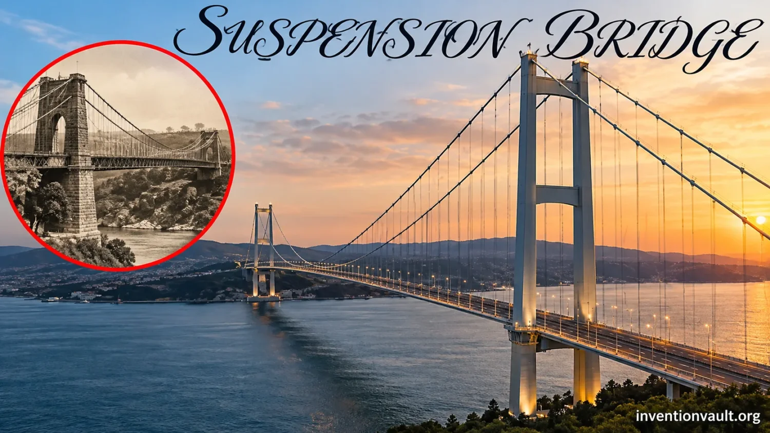
Long-Span Design Evolution
How Suspension Bridges Reached 2 Kilometers
Follow the changes in deck stiffness, iron, wire cables, aerodynamics and construction that turned suspended crossings into record-setting transport structures.
Early structural principle
Suspension Before the Modern Bridge
Current stage
Older principle
Rope and chain crossings carried travelers by hanging a walkway from flexible tension members long before engineers developed the modern road-carrying suspension bridge.
1615 design record
Fausto Veranzio published suspended-bridge proposals using rope and iron-chain arrangements, showing that the structural idea appeared in print well before nineteenth-century road bridges.
Missing feature
A flexible suspended walkway was not yet the later engineered system of a relatively level stiffened deck, hangers, towers, main tension members and controlled anchorages.
The old idea was suspension; the later invention problem was turning suspension into a predictable roadway.
Defining road-bridge system
James Finley’s 1801 Bridge
Current stage
Jacob’s Creek
In 1801 James Finley built a roughly 70-foot bridge over Jacob’s Creek in Pennsylvania with a level, stiffened vehicular deck suspended from wrought-iron chains.
Patent timing
Finley obtained patent protection in 1808. The patent therefore followed the documented bridge rather than marking the first construction date.
Structural distinction
Vertical suspenders transferred deck load to curved iron chains while end anchorage and supports resisted the resulting cable forces. That arrangement closely resembles the load path of later suspension bridges.
Finley’s contribution was not inventing suspended travel, but adapting it into a stiffened road-bridge system.
Large-span chain bridge
Telford Scales the System
Current stage
Main span
Thomas Telford’s Menai Suspension Bridge opened in 1826 with a 579-foot, about 176-meter, span between its towers, then the longest span yet attempted.
Iron chains
Sets of wrought-iron eyebars formed the main suspension chains. Their scale showed that suspended roadways could cross waterways where intermediate supports were undesirable.
Wind weakness
The original roadway lacked adequate stiffening and proved unstable in wind. Strengthening followed, exposing a problem that would remain central as suspension spans became lighter and longer.
Longer spans reduced the need for supports in water, but they made deck movement much harder to ignore.
Material transition
Chains Give Way to Wire
Current stage
1816 experiment
Josiah White and Erskine Hazard erected an unusually narrow wire suspension footbridge across the Schuylkill River in 1816, demonstrating that drawn iron wire could carry a suspended span.
Why wire helped
Large cables could be assembled from many smaller wires rather than relying on a chain of heavy links and pins. The approach offered a better route toward long, high-capacity tension members.
Construction consequence
Parallel wires could eventually be carried across a span repeatedly and gathered into cable strands, allowing engineers to create enormous cables at the bridge site.
The material change created a practical route from iron-chain bridges to the giant main cables of later spans.
Cable-and-deck engineering
Roebling Integrates the System
Current stage
Wire-cable practice
John A. Roebling developed wire-rope manufacture and suspension-bridge construction through a sequence of projects in which cable making, stiffening and erection were treated as connected engineering problems.
Brooklyn span
The Brooklyn Bridge opened in 1883 with a central span of 1,595 feet 6 inches, about 486 meters, supported by four steel-wire main cables.
Cable scale
Historic documentation records 5,434 individual wires in each Brooklyn Bridge main cable, illustrating how thousands of small tensile elements could become one large structural cable.
By the Brooklyn Bridge era, cable manufacture, anchorage, towers and deck stiffness formed one coordinated long-span system.
Kilometer-span era
The Main Span Passes One Kilometer
Current stage
George Washington Bridge
Othmar Ammann’s George Washington Bridge opened in 1931 with a 3,500-foot, about 1,067-meter, main span and nearly doubled the span of the previous record holder.
Golden Gate
The Golden Gate Bridge followed in 1937 with a 4,200-foot, 1,280-meter main span, setting another world record.
Weight pressure
As spans lengthened, reducing structural dead weight became more attractive. The same pursuit of slenderness also made flexibility and wind response harder design problems.
Once spans reached a kilometer, controlling motion became as necessary as carrying static load.
Aerodynamic failure
Tacoma Changes Wind Design
Current stage
Very slender deck
The 1940 Tacoma Narrows Bridge had an 853-meter main span but used only 8-foot-deep plate girders along a deck just 39 feet wide between the cables.
Collapse behavior
On November 7, 1940, wind-driven motion developed into severe torsional oscillation and aeroelastic instability. The event cannot be explained accurately as a simple case of static wind pressure.
Design response
Later long-span design gave much greater attention to deck shape, torsional stiffness, damping, wind-tunnel testing and the interaction between structural movement and airflow.
Tacoma showed that a bridge could satisfy strength calculations yet still fail through unstable interaction with moving air.
Ultra-long-span engineering
Beyond the Two-Kilometer Span
Current stage
Completed record
The 1915 Çanakkale Bridge opened in Türkiye in 2022 with a 2,023-meter main span, the longest main span of any completed suspension bridge.
Bridge under construction
China’s Zhangjinggao Yangtze River Bridge is being built with a 2,300-meter steel-box-girder suspension span. Its southern anchorage main structure was completed in August 2026.
3,300-meter proposal
The Strait of Messina project specifies a 3,300-meter suspended central span. It remained in project and approval procedures in October 2026, so it is not a completed or current record bridge.
The present frontier is governed by cable mass, aerodynamics, anchorage scale, erection control and serviceability across unprecedented distances.
The modern suspension bridge was not invented in a single step. Suspended walkways existed long before industrial bridge engineering, but James Finley’s 1801 Jacob’s Creek Bridge in Pennsylvania is widely treated as a defining early modern form because it combined wrought-iron suspension chains with vertical hangers and a relatively level, stiffened vehicular deck. Finley patented his system in 1808. During the next two centuries, iron chains gave way to wire cables, spans grew from tens of meters to more than two kilometers, decks became lighter, and the problem of wind changed from an afterthought into a central part of long-span design.
Dating the First
Calling Finley the inventor of “the suspension bridge” can be misleading. The suspended-crossing principle is far older. His place in the history is more specific: an early documented modern road bridge with a level stiffened deck hanging from iron chains, followed by an 1808 patent.
| Milestone | Date | What changed |
|---|---|---|
| Fausto Veranzio’s published designs | 1615 | Printed proposals showed suspended decks using rope and iron-chain arrangements. |
| James Finley’s Jacob’s Creek Bridge | 1801 | A level, stiffened road deck was suspended from wrought-iron chains. |
| Finley patent | 1808 | The documented patent followed Finley’s earlier working bridge. |
| White–Hazard wire footbridge | 1816 | Iron wire demonstrated an alternative to heavy chain links. |
| Union Chain Bridge | 1820 | Samuel Brown carried vehicles across a much larger wrought-iron chain span. |
| Menai Suspension Bridge | 1826 | Thomas Telford pushed the main span to about 176 meters. |
| Brooklyn Bridge | 1883 | Large steel-wire cables and stiffening methods supported a roughly 486-meter central span. |
| George Washington Bridge | 1931 | The world-record main span passed one kilometer. |
| Golden Gate Bridge | 1937 | The record increased to 1,280 meters. |
| Tacoma Narrows collapse | 1940 | Aeroelastic behavior forced a reassessment of long, slender suspended decks. |
| Akashi Kaikyo Bridge | 1998 | The completed-span record reached 1,991 meters. |
| 1915 Çanakkale Bridge | 2022 | The completed record passed two kilometers at 2,023 meters. |
Suspension Existed Before the Modern Suspension Bridge
The basic idea is easy to create without towers of steel or massive concrete anchorages. Stretch flexible members across a gap and support a walkway from them. Variations of rope suspension crossings developed in different regions because tension members could cross terrain where masonry arches, timber beams or intermediate piers were difficult to build.
That history makes the word invention unusually slippery here. A rope crossing in which the walking surface follows a flexible curve is structurally related to a modern suspension bridge, but it does not contain the complete road-bridge system that later engineers needed for horses, wagons, trains and motor traffic.
Europe also had conceptual designs before Finley. In 1615, Fausto Veranzio published bridge proposals that included a deck carried from a rope catenary and another arrangement involving iron chains. Such drawings demonstrate that suspending a deck from curved tension members was already understood as a bridge concept. They do not, by themselves, establish a continuously used modern long-span bridge tradition.
What Different Evidence Actually Establishes
- Traditional suspended crossingsShow that the physical principle of hanging a crossing from flexible tension members predates nineteenth-century bridge engineering.
- Published bridge designsShow that a designer described or illustrated an arrangement, but do not prove that the proposed structure was built at full scale.
- Completed road bridgesDemonstrate that the structural arrangement could carry practical traffic under real conditions.
- Patent recordsDocument a legal claim at a particular date; they should not automatically be treated as the date on which a working bridge first existed.
James Finley and the Level-Deck Road Bridge
James Finley’s importance comes from the way he reorganized the suspended crossing into a usable road structure. Historic American Engineering Record documentation identifies his 1801 Pennsylvania bridge as the first modern suspension bridge and describes a level deck hanging from wrought-iron chains supported between towers. The roughly 70-foot span was small compared with later bridges, but its structural arrangement pointed toward the form that would dominate extreme spans.
The deck itself mattered. A traveler does not want a wagon road to sag like a freely hanging rope. Finley’s bridge used a stiffened deck carried by vertical suspenders connected to curved iron chains. The chains carried tension. Supports redirected their forces. Anchorages at the ends resisted the horizontal pull generated by the suspended system.
Finley obtained a patent in 1808, seven years after the Jacob’s Creek bridge. An 1810 engraving credited to William Strickland and Benjamin Tanner shows another Finley chain bridge and includes construction details for the suspenders and the chain support over the uprights. That surviving visual record helps explain why Finley’s contribution is more specific than the vague claim that he simply “invented hanging bridges.”
Why a stiffened deck changed the problem
A freely suspended floor responds easily to a moving concentrated load. When a horse, wagon or group of travelers changes position, the load distribution changes with it. A stiffening system spreads that local load over a larger part of the span and limits changes in deck shape.
This does not make the deck independent of the chains. It makes the two systems cooperate. The suspended elements carry much of the vertical load through tension, while the stiffened roadway distributes loads and limits local deformation. That interaction became more demanding as bridges grew longer, lighter and more exposed to wind.
Iron Chains Made Large Road Spans Possible
The next advance was not a completely new bridge form. Engineers had to scale the suspended roadway far beyond Finley’s short crossings while maintaining reliable chains, towers and anchorages.
Samuel Brown and the Union Chain Bridge
The Union Chain Bridge across the River Tweed opened in 1820. Designed by Samuel Brown, it used wrought-iron chains and carried horse-drawn traffic across a 437-foot span between its pylon tops. Its survival also makes it a rare physical connection to the first generation of large vehicular suspension bridges.
Brown had experience manufacturing wrought-iron anchor chains. That industrial background was directly relevant to bridge design: a long suspension bridge required reliable iron tension members, connections and fabrication methods rather than only a structural sketch.
Thomas Telford’s Menai Bridge pushed the span to 579 feet
The Menai Suspension Bridge opened in 1826 as part of the road route toward Holyhead. Its main span measured 579 feet, about 176 meters, from tower to tower. Thomas Telford used sets of wrought-iron eyebars joined into chains, with the roadway suspended below them.
The span showed why the suspension form attracted engineers. A wide navigable waterway could be crossed without placing a forest of supports beneath the roadway. Larger spans concentrated structural work into towers, cables or chains, anchorages and the suspended deck.
Menai also exposed an issue that became more serious with every later attempt to save weight. Its original roadway had no adequate stiffening trusses and proved unstable in wind. The deck was strengthened in 1840, and a steel deck later replaced the timber deck. Longer did not automatically mean better behaved.
Why Wire Cables Replaced Giant Chains
A chain cable consists of discrete links, plates, pins and joints. That works, but every component adds weight and every connection becomes part of the load path. As spans grow, the bridge must support not only traffic and roadway weight but also an enormous quantity of its own suspension material.
Wire offered another path. In 1816, Josiah White and Erskine Hazard built a narrow pedestrian suspension bridge across the Schuylkill River using iron wire. It was experimental rather than a heavy road bridge, yet it demonstrated a principle with enormous future value: a main suspension element could be assembled from many relatively small wires.
That distinction becomes more useful as the cable grows. Instead of forging, moving and joining a few enormous chain members, bridge builders can combine many high-strength wires into strands and combine strands into a cable. Damage to one wire does not represent the same configuration as breaking the single weakest link in a chain, although wire-cable durability brings its own inspection and corrosion problems.
From iron wire to high-strength steel cable
The material shift took decades. Better wire manufacture, higher tensile strength and improved cable-making practice allowed cables to carry larger loads without an equivalent increase in structural weight. Charles Ellet and John A. Roebling were among the engineers who pushed wire suspension bridges further during the nineteenth century.
Roebling’s work is especially relevant because cable manufacture, erection method and bridge behavior became parts of the same design problem. A long cable was not simply ordered as one finished object and lifted into position. Its thousands of wires had to be manufactured, transported, placed across the span, gathered, compacted and protected.
The Brooklyn Bridge Shows the Mature Nineteenth-Century System
When the Brooklyn Bridge opened in 1883, its approximately 486-meter central span was supported by four steel-wire main cables. Historic documentation records 5,434 individual wires in each cable.
The bridge is often remembered for its masonry towers, but the more relevant invention story lies in the system between them. Main cables transmitted suspended loads toward the anchorages. Vertical suspenders linked the deck to the main cables. The deck required enough stiffness to distribute traffic loads and resist deformation. Massive end anchorages provided the reaction needed to prevent the cables from simply pulling inward.
Roebling’s bridge work also illustrated an idea that remains central to ultra-long spans: the cable cannot be separated conceptually from the method used to build it. The geometry required by the finished bridge has to be achieved during erection while the weight carried by the cable changes step by step.
How a Suspension Bridge Carries Load
A suspension bridge looks complex because much of its structure is curved or hanging, but its primary gravity-load path can be followed in a short sequence.
- Deck receives the loadTraffic, pavement, structural self-weight and other vertical loads first act on the roadway and its supporting floor system.
- Hangers pull on the main cablesVertical or near-vertical suspenders transfer deck forces upward into the curved main cables.
- Main cables carry tensionThe cables redirect distributed vertical loads toward the towers and anchorages while remaining predominantly in tension.
- Towers carry compressionAt each tower, cable forces create large downward reactions that the tower carries toward its foundation.
- Anchorages resist cable pullAt the ends of a conventional earth-anchored suspension bridge, massive anchorages resist the horizontal component of main-cable tension and transfer it into the ground.
| Bridge element | Main structural job | Why it matters as span grows |
|---|---|---|
| Main cables | Tension | They must carry enormous load while their own weight also becomes part of the load. |
| Suspenders | Tension | They transfer deck loads into the main cable at many points. |
| Towers | Mostly compression | Long spans demand high cable elevations and very large tower reactions. |
| Anchorages | Resist main-cable pull | Cable tension can require enormous concrete and foundation systems. |
| Deck and stiffening system | Bending, torsion and load distribution | It must remain light without becoming too flexible under traffic and wind. |
| Foundations | Transfer reactions into ground | Deep water, weak soil and very large forces can control the entire project. |
Why the main cable hangs in a curve
A flexible cable cannot resist bending in the way a rigid beam does. Its useful structural action comes from tension, so its geometry changes until the tension forces can balance the applied loads.
Two curves are often mentioned. An ideal cable carrying only its own weight, distributed along the cable itself, takes a catenary shape. When the dominant load is treated as uniformly distributed across the horizontal bridge span, the cable is commonly approximated as a parabola. A real suspension-bridge cable carries several kinds of load, so those mathematical forms are useful idealizations rather than a claim that every cable exactly follows one simple curve.
For an ideal parabolic cable carrying a uniform load per unit of horizontal span, the horizontal component of cable tension can be represented approximately by H ≈ wL2/(8f), where L is span, f is sag and w is the distributed load. The relation explains an important design tradeoff: reducing sag while keeping the same span and load raises horizontal cable force sharply.
Why Suspension Bridges Became the Choice for Extreme Spans
A beam spanning a huge gap develops large bending effects and requires material far from its neutral axis to resist them. The suspension bridge approaches the problem differently. Its primary span-carrying elements are cables working efficiently in tension.
That does not mean suspension bridges are automatically light. Towers, cables, deck, anchorages and foundations can contain enormous quantities of material. Their advantage appears when the gap becomes so large that placing intermediate piers is difficult and other bridge forms would require much heavier span structures.
Long spans also help keep navigation channels open. For deep straits, busy shipping routes or wide river channels, reducing the number of foundations in the water can outweigh the cost and complexity of the suspension system.
From Brooklyn to the One-Kilometer Span
Long-span records did not advance because one new component suddenly appeared. Steel quality improved, cable wire became stronger, structural analysis became more capable and erection control became more accurate. Engineers also learned how much dead weight could be removed from decks without making them unacceptably flexible.
George Washington Bridge: 1,067 meters
Othmar Ammann’s George Washington Bridge opened in 1931 with a 3,500-foot main span, about 1,067 meters. Historic American Engineering Record documentation describes it as the longest-span suspension bridge in the world when constructed. Its span was nearly twice that of its largest predecessor.
Crossing the kilometer threshold changed the scale of the design problem. The weight of the structure itself was becoming an ever-larger share of the load that the suspension system had to carry. Removing unnecessary material could therefore produce benefits that propagated through the cables, towers and foundations.
Golden Gate Bridge: 1,280 meters
The Golden Gate Bridge opened to vehicles in 1937 with a 4,200-foot, 1,280-meter main span. It held the world record until the Verrazzano-Narrows Bridge opened in 1964 with a 4,260-foot span.
The Golden Gate also provides an intuitive picture of suspension mechanics. Its main cables are pulled in tension, while its towers carry large compressive reactions. Each anchorage has to resist the cable forces delivered at the ends. The bridge is therefore not simply a roadway hanging from two ropes; it is a continuous force-transfer system extending from one foundation to the other.
Tacoma Narrows Proved That Strength Was Not Enough
The first Tacoma Narrows Bridge opened in Washington State in July 1940 with a main span of 2,800 feet, about 853 meters. It represented the contemporary push toward slender, economical suspension bridges. Its roadway was only 39 feet wide between the main cables, and its stiffening plate girders were just 8 feet deep.
Those proportions made the bridge remarkably flexible. Even before the collapse, the deck developed noticeable vertical movement in wind. Engineers tried measures intended to suppress the motion, but the underlying aerodynamic behavior had not yet been understood adequately.
On November 7, 1940, the bridge entered severe torsional motion before the suspended structure failed. The familiar classroom statement that the wind simply “matched the bridge’s natural frequency” is too crude. The failure involved interaction between airflow and the moving deck, with aeroelastic instability becoming central to the collapse.
Not Just Simple Resonance
The Tacoma Narrows collapse should not be reduced to wind periodically pushing the bridge at exactly one natural frequency. The deck’s motion altered the aerodynamic forces acting on it, producing a coupled torsional instability that ordinary static wind calculations could not capture.
What changed after Tacoma
Suspension-bridge design could no longer treat wind mainly as a sideways static pressure to be resisted by enough structural strength. Engineers had to study how air moved around the deck and how the deck’s own motion changed those aerodynamic forces.
Wind-tunnel testing became part of the design process for major long-span bridges. Engineers investigate vertical bending, torsion, vortex-induced movement, flutter, buffeting and the effect of turbulent winds. The shape of the deck can therefore be as relevant as the quantity of steel inside it.
Three broad responses recur in long-span wind design: change structural stiffness, alter damping, or modify the aerodynamic form so that airflow produces a more stable response. Modern projects combine these rather than treating them as mutually exclusive choices.
The Deck Became an Aerodynamic Component
Nineteenth-century and early twentieth-century suspension bridges often used deep stiffening trusses. Later bridges could use streamlined steel box girders whose external geometry was designed with airflow in mind.
This created a demanding balance. A very deep, heavy deck adds dead load. An excessively light and flexible deck can respond poorly to wind. The desired structure has enough bending and torsional stiffness for serviceability and aerodynamic stability without wasting mass that the cables, towers and foundations must support for the bridge’s entire life.
Orthotropic steel decks reduce dead weight
An orthotropic steel deck combines the roadway plate with longitudinal ribs and transverse structural members so the plate becomes part of the load-carrying deck system. Its low weight makes it especially useful where every tonne removed from the suspended span also reduces demand elsewhere in the bridge.
That advantage explains its use in long-span construction and in some redecking projects. The tradeoff is demanding fabrication and fatigue design: welded details repeatedly experience wheel loads, so lightness cannot be separated from fatigue resistance, inspection and maintenance.
Building the Bridge Requires the Cable Before the Roadway
A completed suspension bridge looks as if the deck supports traffic and the cables merely hold it up. Construction proceeds in almost the opposite order. The main suspension system has to exist before most of the suspended roadway can be placed.
- Build foundations and anchoragesTower foundations and cable anchorages establish the locations that will eventually receive immense structural reactions.
- Erect the towersThe towers create the high points over which the main cables pass and must be ready before the completed cable geometry can be formed.
- Carry a pilot line acrossA light initial line provides a route for later ropes, temporary catwalk systems and cable-installation equipment.
- Install or spin the main cablesThousands of wires may be carried across the span and assembled into strands, then compacted and protected to form the main cables.
- Attach suspendersHangers are connected between the main cables and the future deck locations.
- Erect deck sectionsPrefabricated deck units can be lifted from barges or delivered from the approaches, connected to the suspenders and joined into the continuous roadway structure.
Every added deck segment changes the loads carried by the cables and towers. Surveying, cable geometry and erection calculations therefore have to anticipate the final loaded shape rather than merely positioning components according to an unloaded drawing.
The Main-Span Record Grew from About 21 Meters to 2,023
Main span is the useful measurement when comparing the distance a suspension bridge crosses between its primary towers. Total bridge length can include side spans, approaches and viaducts and therefore does not describe the same engineering challenge.
| Bridge | Opened | Main span | Design step represented |
|---|---|---|---|
| Jacob’s Creek Bridge | 1801 | About 21 m | Early modern level-deck iron-chain road bridge |
| Union Chain Bridge | 1820 | About 133 m | Large wrought-iron chain vehicular span |
| Menai Suspension Bridge | 1826 | About 176 m | World-record chain suspension span |
| Brooklyn Bridge | 1883 | About 486 m | Large steel-wire cable system |
| George Washington Bridge | 1931 | 1,067 m | Main span passes one kilometer |
| Golden Gate Bridge | 1937 | 1,280 m | New prewar span record |
| Verrazzano-Narrows Bridge | 1964 | 1,298 m | Golden Gate record exceeded |
| Humber Bridge | 1981 | 1,410 m | Span record moves beyond 1.4 km |
| Great Belt East Bridge | 1998 | 1,624 m | Large aerodynamic steel-deck generation |
| Akashi Kaikyo Bridge | 1998 | 1,991 m | Record approaches two kilometers |
| 1915 Çanakkale Bridge | 2022 | 2,023 m | First completed suspension span beyond two kilometers |
The progression is not smooth because main-span records depend on geography, traffic demand, economics and available projects as much as structural capability. Still, the scale change is clear. The roughly 21-meter Finley span and the 2,023-meter Çanakkale span use recognizably related force paths while differing radically in materials, analysis, aerodynamics, fabrication and construction control.
Akashi Kaikyo Brought the Record to 1,991 Meters
Japan’s Akashi Kaikyo Bridge opened in 1998 with a 1,991-meter central span. The bridge crosses the Akashi Strait, where deep water, strong tidal currents, heavy marine traffic, wind and earthquake risk all affected the engineering.
The central span had originally been designed at 1,990 meters. During construction, the 1995 Hyogo-ken Nanbu earthquake shifted the tower locations enough that the span became 1,991 meters. Inspection found no major bridge damage, but the geometry had changed and the project was adjusted accordingly.
Its scale also illustrates why modern long-span design is more than a larger copy of a nineteenth-century bridge. Wind response had to be tested, deep-water foundations built, cable forces controlled and a nearly two-kilometer suspended girder erected accurately across a busy strait.
1915 Çanakkale Crossed the Two-Kilometer Barrier
The 1915 Çanakkale Bridge opened on March 18, 2022 across the Dardanelles in Türkiye. Its main span is 2,023 meters, giving it the longest main span among completed suspension bridges.
That measurement needs to remain precise. The record concerns the distance between the main towers, not total bridge length. Other bridges can be longer overall because they include long approach structures or multiple spans without exceeding Çanakkale’s individual suspended main span.
Crossing two kilometers does not remove the old suspension-bridge problems. It magnifies them. Cable self-weight becomes enormous. A small change in deck mass is repeated over kilometers. Wind acts across an exceptionally long flexible structure. Temperature changes alter cable and deck geometry. Construction tolerances have to be controlled across distances that dwarf the earliest iron-chain bridges.
The Next Record Bridge Is Already Under Construction
The next main-span record is not merely a conceptual sketch. China’s Zhangjinggao Yangtze River Bridge project includes a 2,300-meter steel-box-girder suspension bridge across the main navigation channel of the Yangtze.
Chinese transport authorities describe it as the largest-span bridge currently under construction. The project uses approximately 350-meter suspension-bridge towers and is planned to connect Zhangjiagang, Jingjiang and Rugao in Jiangsu. Earlier project information gives 2028 as the expected completion year.
Construction had moved well beyond preliminary work by 2026. On August 25, 2026, the main structure of the southern anchorage was completed. The anchorage body exceeds one million tonnes and was built over a huge foundation in deep, weak alluvial ground. Project reporting at that stage said work would move toward operations needed for the upper structure, including pilot-line crossing, catwalk erection, main cables and steel-box deck construction.
| Ultra-long-span project | Planned or completed main span | Status |
|---|---|---|
| 1915 Çanakkale Bridge, Türkiye | 2,023 m | Open to traffic; completed main-span record |
| Zhangjinggao Yangtze River Bridge, China | 2,300 m | Under construction |
| Strait of Messina Bridge, Italy | 3,300 m | Project and approval process; not a completed bridge |
A 3,300-Meter Suspension Span Is Being Pursued for Messina
The proposed Strait of Messina crossing would move the scale much farther. Current design information from Stretto di Messina specifies a 3,300-meter central suspended span, 399-meter towers and four main suspension cables, each 1.26 meters in diameter and composed of 44,323 steel wires.
The proposed deck is 60.4 meters wide and is intended to carry road lanes, service lanes and two railway tracks. Rail traffic makes serviceability especially demanding because trains place tighter limits on deformation and track geometry than ordinary road vehicles.
The project’s status must be separated from its design dimensions. Italy’s infrastructure ministry reported an operational meeting on October 2, 2026 concerning the technical, economic and administrative documentation for the project. Stretto di Messina had also reported progress through regulatory and engineering review stages during 2026. A 3,300-meter span therefore belongs to the active long-span frontier, but it should not be described as an existing world-record bridge.
Why 3,300 Meters Is Not Simply 2,023 Meters Made Larger
Scaling a suspension span upward creates feedback between structural choices. A longer cable weighs more. Carrying that additional cable mass requires cable capacity. A heavier deck increases cable tension and tower reaction. Larger cable forces demand larger anchorage and foundation capacity.
Wind behavior also changes because natural frequencies, deck flexibility and aerodynamic response depend on span, mass, stiffness and geometry. A cross-section that performs well at one scale cannot be assumed to remain satisfactory after the span is extended by another kilometer.
Rail adds another layer. A highway deck can tolerate movements that would be undesirable for high-quality railway alignment. A combined road-and-rail ultra-long span therefore has to reconcile structural flexibility with train-running requirements, while also addressing wind and seismic actions.
Construction becomes its own scaling problem. Pilot cables must cross larger distances. Catwalks, wire-spinning operations and deck lifting take place at greater heights and over a broader weather-sensitive work zone. Survey errors that appear tiny locally can matter when geometry is controlled over several kilometers.
Suspension Bridge and Cable-Stayed Bridge Are Not the Same System
Both bridge types use cables and towers, so they are often confused. Their load paths are different.
Suspension Bridge
A continuous curved main cable passes over the towers and, in an earth-anchored design, continues toward large end anchorages. Hangers suspend the deck from that main cable.
Cable-Stayed Bridge
Multiple inclined stays connect the deck more directly to the towers. The familiar separate main cable and vertical-hanger system is absent.
Cable-stayed bridges have become competitive for many long crossings, but suspension bridges remain especially suited to the most extreme main spans. The 2,023-meter Çanakkale bridge, the 2,300-meter Zhangjinggao bridge under construction and the proposed 3,300-meter Messina crossing all use the suspension form.
There is no universal span length at which one bridge type suddenly becomes correct and the other becomes wrong. Site conditions, stiffness requirements, foundation locations, navigation, construction method, traffic and economics all affect the choice.
The Modern Main Cable Is Also a Durability System
Thousands of high-strength wires solve the strength-and-weight problem only if those wires remain protected. Water entering a main cable can promote corrosion in places that are difficult to inspect directly.
Modern cable management can therefore include tightly compacted wire bundles, protective wrapping or sheathing, sealed details and dehumidification systems that circulate dry air through cable spaces. Older suspension bridges have also received cable dehumidification during rehabilitation.
This is a major difference between imagining a cable as a simple steel rope and treating it as a century-scale infrastructure component. Its mechanical capacity, corrosion protection, inspection strategy and replaceability of related components all have to be considered together.
Each Record Exposed the Next Design Limit
| Development stage | Problem exposed | Engineering response |
|---|---|---|
| Flexible rope crossings | Unstable walking surface and limited load capacity | Stiffer decks and iron tension members |
| Finley-type chain bridges | Need to carry wheeled traffic on a level roadway | Stiffened suspended deck and organized hanger system |
| Large wrought-iron chain bridges | Heavy chains, many joints and scaling limits | Development of wire-cable systems |
| Nineteenth-century wire suspension | Need to manufacture and erect much larger cables | Wire spinning, strand assembly and improved steel |
| Kilometer-span bridges | Dead weight and deck flexibility | Higher-strength materials and weight-efficient structures |
| Tacoma Narrows era | Aeroelastic instability | Wind-tunnel testing, deck-shape control, stiffness and damping |
| Late twentieth-century mega-spans | Weight, wind, deep-water construction and seismic demand | Aerodynamic steel decks, refined analysis and large-scale testing |
| Two-kilometer-plus spans | Cable mass, anchorage size, erection accuracy and serviceability | Integrated aerodynamic, geotechnical, material and construction engineering |
The history of the suspension bridge is therefore better understood as a sequence of solved limits than as a single invention date. Finley’s bridge supplied an early recognizable modern road-bridge arrangement. Telford showed that iron-chain suspension could cross much larger waterways. Wire replaced chain as the route to still greater spans. Roebling-era engineering tied cable manufacture to deck stiffness and erection. Twentieth-century bridges pushed the span beyond a kilometer, and Tacoma forced wind behavior into the design process. Modern cable, deck, foundation and aerodynamic engineering then made two-kilometer spans possible.
The same structural idea remains visible throughout that progression: a roadway sends its load through hangers into curved tension members, towers and anchorages. What changed was the ability to predict, manufacture, erect and control that system at scales the earliest builders could not reach.
Questions People Ask About the Invention of the Suspension Bridge
Who is usually credited with inventing the modern suspension bridge?
James Finley is widely associated with the first modern suspension bridge because his 1801 Jacob’s Creek Bridge used a level, stiffened vehicular deck hung by vertical suspenders from wrought-iron chains. The broader principle of suspended crossings is much older, so describing Finley as the inventor of every form of suspension bridge would be too broad.
Was the suspension bridge invented in 1801 or 1808?
The dates refer to different events. Finley’s Jacob’s Creek Bridge was built in 1801. He received patent protection for his bridge system in 1808. The patent date should therefore not replace the earlier construction date.
Why did suspension bridges change from chains to wire cables?
Wire allowed large tension members to be assembled from thousands of smaller high-strength elements. This offered a more practical path toward very large, relatively light main cables than scaling link-and-pin chains indefinitely.
Did Tacoma Narrows collapse because of resonance?
Simple forced resonance is not an adequate explanation. The bridge developed severe torsional motion involving aeroelastic interaction between the moving deck and airflow. The disaster helped establish aerodynamic stability as a required part of long-span bridge engineering.
What is the longest completed suspension bridge main span?
The 1915 Çanakkale Bridge in Türkiye has a 2,023-meter main span and has held the completed suspension-bridge main-span record since opening in 2022.
Will the 2,023-meter record be broken?
The Zhangjinggao Yangtze River Bridge in China is under construction with a planned 2,300-meter main span. If completed to that design, it will exceed the 1915 Çanakkale Bridge’s main-span record. The Strait of Messina project is designed for an even larger 3,300-meter central suspended span but should be treated separately because it has not yet become a completed bridge.
References Used for This Article
- Library of Congress, Historic American Engineering Record — Maine’s Nineteenth-Century Suspension Bridges — used for James Finley’s 1801 bridge, the 1808 patent distinction and the transition toward wire-cable suspension bridges.
- Library of Congress — View of the Chain Bridge invented by James Finley Esqr. — used for the surviving 1810 engraving and its suspension-detail documentation.
- American Society of Civil Engineers — Union Chain Bridge — used for Samuel Brown, the 1820 completion date and 437-foot chain span.
- American Society of Civil Engineers — Menai Suspension Bridge — used for the 579-foot span, wrought-iron eyebar chains and early wind-instability history.
- National Park Service documentation — Brooklyn Bridge — used for the central-span dimensions, four steel main cables and wire count.
- American Society of Civil Engineers — George Washington Bridge — used for the 3,500-foot main span and 1931 record.
- Golden Gate Bridge, Highway and Transportation District — Design & Construction Statistics — used for the 1,280-meter main-span dimension and structural data.
- Washington State Department of Transportation — 1940 Tacoma Narrows Bridge history — used for deck width, 8-foot plate girders, span dimensions and the bridge’s unusually slender proportions.
- Federal Highway Administration — Steel Orthotropic Bridge Decks — used for the low-weight advantage and long-span applications of orthotropic steel decks.
- Storebælt — Facts & History — used for the Great Belt East Bridge’s 1,624-meter main span.
- JB Honshu-Shikoku Bridge Expressway Company — Akashi-Kaikyo Bridge — used for the 1,991-meter central span, 1998 completion and long-span environmental design conditions.
- Guinness World Records — Longest Suspension Bridge Span — used to verify the 2,023-meter completed record of the 1915 Çanakkale Bridge and its March 18, 2022 opening date.
- Ministry of Transport of the People’s Republic of China — Zhangjinggao Yangtze River Bridge construction update — used for the 2,300-meter span and August 2026 southern-anchorage construction status.
- Stretto di Messina S.p.A. — Bridge Final Design — used for the proposed 3,300-meter span, 399-meter towers, four 1.26-meter cables, wire count and deck dimensions.
- Italian Ministry of Infrastructure and Transport — Strait of Messina project update, October 2, 2026 — used to distinguish the project’s current administrative and technical status from that of a completed bridge.