
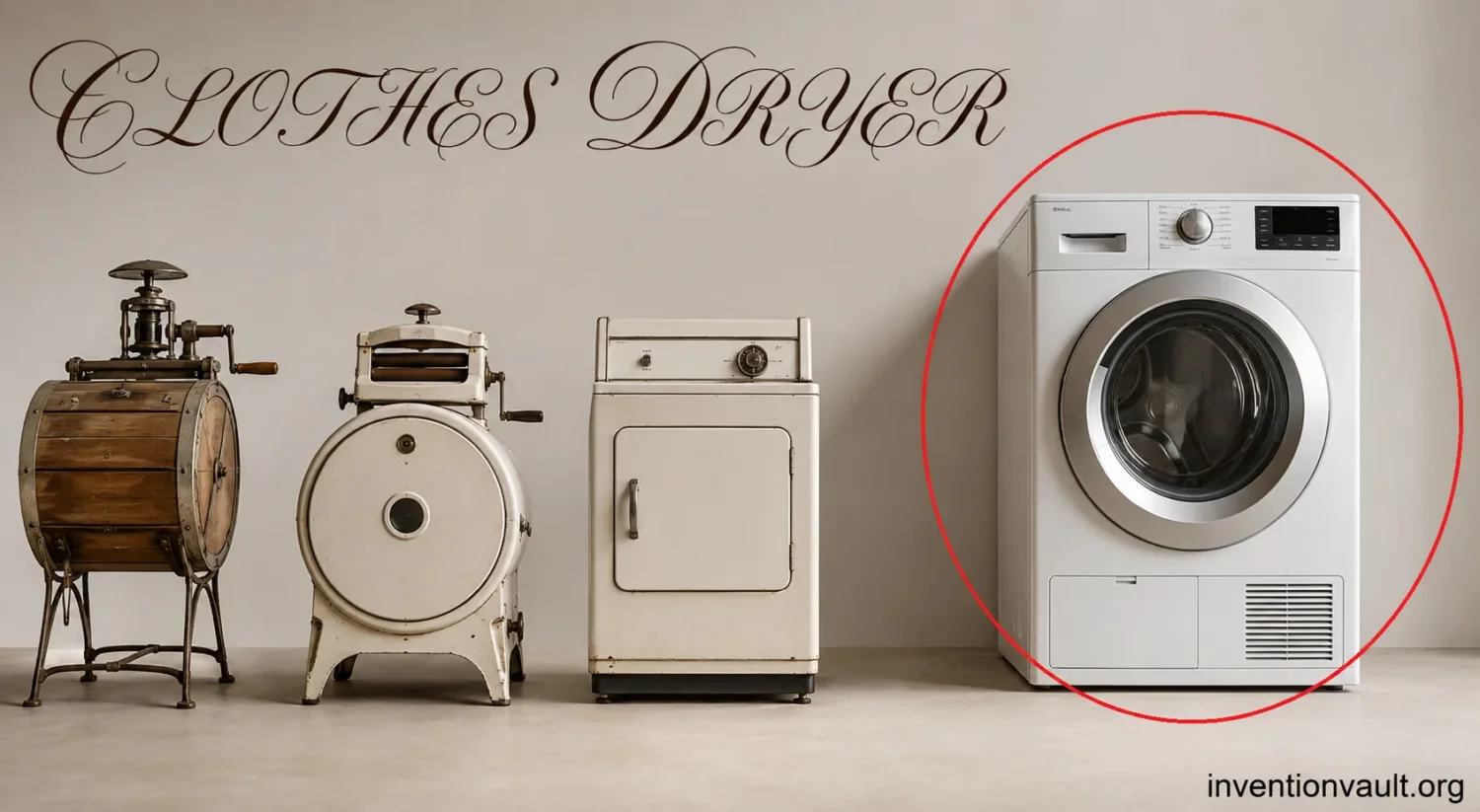
Laundry System Build Map
How Fast Drying Became a Machine
Trace how enclosed heat, moving textiles, forced air, automatic control, and heat recovery formed the clothes dryer.
Baseline method
Open-Air Drying
Selected file: Open-Air Drying. Choose another file to update this evidence card.
Selected
Moisture route
Water leaves wet fibers by evaporation, then diffuses into the surrounding air. Warmth, low humidity, air movement, fabric thickness, and available surface area determine the pace.
Practical limit
Rain, freezing weather, polluted air, weak ventilation, and limited indoor space can interrupt drying even after washing and wringing are complete.
Unsolved task
Fast indoor drying required a dependable source of heat and airflow without scorching textiles, filling rooms with moisture, or demanding constant handling.
The dryer began as an attempt to control the conditions that outdoor air supplied unevenly.
Enclosed heating
Heated Drying Closets
Selected file: Heated Drying Closets. Choose another file to update this evidence card.
Selected
Documented example
An 1878 Thomas Bradford & Co. catalog shows stove-assisted drying closets sold for homes, schools, hospitals, hotels, and other institutions.
Design move
Placing hanging laundry inside a warmed cabinet reduced dependence on outdoor weather and concentrated heat around the load.
Remaining weakness
Stationary garments could shield one another, moisture still needed an escape path, and the operator had to arrange and remove each item.
The closet controlled heat, but it did not yet combine fabric motion with a managed air circuit.
Patent evidence
George T. Sampson’s Folding Rack
Selected file: George T. Sampson’s Folding Rack. Choose another file to update this evidence card.
Selected
Recorded date
U.S. Patent No. 476,416 was issued to George T. Sampson of Dayton, Ohio, on June 7, 1892, after an application filed on June 24, 1891.
Actual geometry
The patent describes hinged wire drying frames positioned close to a stove. The assembly could fold away and also included hooks for cooking utensils.
Credit boundary
Sampson patented an improvement to stove-assisted drying, not a motor-driven rotating drum, blower-controlled air path, or automatic moisture-sensing appliance.
Design value
The device provided a compact, documented way to hold garments near controlled household heat without turning a perforated barrel over an exposed fire.
Sampson’s record is firm, but its mechanism differs sharply from the later automatic tumble dryer.
Mechanical integration
The Powered Tumble Drum
Selected file: The Powered Tumble Drum. Choose another file to update this evidence card.
Selected
Moore’s contribution
J. Ross Moore is widely credited with an electric clothes-dryer design developed in the 1930s; Hamilton Manufacturing began producing his design in 1938.
Load movement
A motorized horizontal drum repeatedly lifts and drops garments, opening temporary air spaces and exposing changing fabric surfaces to heat and moving air.
Patent trail
Moore’s later U.S. Patent No. 2,385,222, issued in 1945 from applications dating to 1936 and 1937, describes tumbling, heating, and vapor removal as one machine.
Manufacturing threshold
The appliance needed more than a drum: motors, bearings, belts, sheet-metal cabinets, heaters, fans, switches, and thermal protection had to work as one repeatable product.
Powered tumbling turned drying from a heated storage task into a continuous heat-and-mass-transfer process.
Air and moisture path
Forced-Air Drying Circuit
Selected file: Forced-Air Drying Circuit. Choose another file to update this evidence card.
Selected
Heat input
Electric resistance elements or a gas burner raise the air temperature, lowering its relative humidity and increasing its capacity to receive water vapor from textiles.
Fan duty
A blower draws air through the heater, drum, lint filter, and exhaust or condensation path. Restricted flow lengthens cycles and can raise temperatures.
Drum duty
Internal baffles lift the load until gravity makes it fall. The repeated motion prevents a dense wet bundle from presenting only its outer surface to the air.
Water exit
Vented machines discharge humid air outdoors; condenser and heat-pump machines turn the vapor back into liquid water for a drain or collection tank.
Fast drying depends on moving vapor away from fabric, not merely making the drum hotter.
Automatic termination
Moisture and Temperature Control
Selected file: Moisture and Temperature Control. Choose another file to update this evidence card.
Selected
Timer problem
A fixed cycle cannot know whether the load is small, heavy, partly dry, or made from absorbent fabric, so it may stop early or continue after drying is complete.
Moisture reading
Many sensor dryers use conductive bars contacted by damp laundry; others infer dryness from exhaust humidity and temperature behavior as evaporation declines.
Heat protection
Operating thermostats regulate cycle temperature, while high-limit devices and thermal cutoffs respond when airflow loss or component failure creates abnormal heat.
Cycle result
Automatic termination reduces needless heating after the selected dryness level is reached, limiting energy waste and prolonged thermal and mechanical exposure.
Control systems made the dryer responsive to the load instead of treating every batch as identical.
Closed-loop drying
Heat-Pump Moisture Recovery
Selected file: Heat-Pump Moisture Recovery. Choose another file to update this evidence card.
Selected
Air reuse
Rather than sending the full stream of warmed air outside, a heat-pump dryer recirculates process air through a closed path.
Cold-side task
The evaporator cools humid return air below its dew point, condensing water that can be drained or collected.
Hot-side task
The condenser returns recovered heat to the now-drier air before it re-enters the drum, reducing demand for new resistance heat.
Trade-off
Lower-temperature closed-loop drying can use far less energy, though cycle time, heat-exchanger cleaning, purchase cost, and room conditions still affect the result.
The newest change is not faster heating but recovering heat that earlier vented designs discarded.
The clothes dryer was not invented in one moment. Heated cabinets and stove-adjacent racks came before powered drum machines; George T. Sampson patented a folding stove-heated rack in 1892, while J. Ross Moore’s electric tumble-dryer work reached manufacture through Hamilton Manufacturing in 1938. The familiar appliance emerged when rotation, controlled heat, forced airflow, moisture removal, and automatic stopping were combined in a cabinet that could be produced and installed safely.
| Question | Best-supported answer |
|---|---|
| Who invented the clothes dryer? | No single inventor created every part of the modern appliance. Early heated enclosures, Sampson’s patented rack, Moore’s powered machine, and later airflow and control designs each solved a different problem. |
| What did George T. Sampson patent? | U.S. Patent No. 476,416, issued June 7, 1892, covered foldable frames that suspended clothing close to a stove. |
| Who is associated with the early electric tumble dryer? | J. Ross Moore is widely credited with a 1930s electric design manufactured by Hamilton Manufacturing from 1938. |
| What makes a tumble dryer work? | A rotating drum exposes wet fabric to heated moving air while a fan carries moisture to an exhaust, condenser, or heat-pump circuit. |
| What are the main modern forms? | Vented electric, vented gas, conventional condenser, and heat-pump dryers. |
Who Invented the Clothes Dryer?
The most accurate answer depends on what counts as a dryer. A warmed room, a drying closet, a hand-turned ventilator, a patented stove rack, and an automatic tumble appliance all remove water from laundry, but they do so with different hardware and levels of control. Treating them as the same invention creates a misleading single-name story.
Dating the First
Later histories often describe perforated hand-cranked drums used in France or England around 1800. The attribution is less firmly documented than surviving patents and trade catalogs, so it should be treated as an early-design tradition rather than a settled sole-inventor claim.
George T. Sampson’s 1892 Patent
George T. Sampson’s patent provides a clear date and a clear mechanism. Filed in 1891 and issued in 1892, it describes a cast support fixed behind a stove, with hinged wire frames that could be lowered into a horizontal drying position and folded away afterward. The patent’s stated purpose was to suspend clothing close to stove heat in a compact arrangement.
That design deserves precise credit. It improved indoor stove-assisted drying and left a surviving legal and technical record. It was not a motorized tumble dryer, and the patent does not describe a blower, rotating drum, moisture sensor, or self-terminating cycle. Calling it the first automatic clothes dryer reads later machinery back into a different device.
J. Ross Moore and the Powered Dryer
J. Ross Moore is widely credited with developing an electric clothes dryer during the 1930s. Museum records state that Hamilton Manufacturing began producing his design in 1938. A later Moore patent, U.S. Patent No. 2,385,222, was issued in 1945 from filings connected to work begun in 1936 and 1937. It describes a clothes-drying machine that tumbles the load, heats the drying chamber, and removes vapor.
Moore’s work belongs closer to the lineage of the modern tumble dryer because it integrated powered motion and controlled drying inside one machine. Even here, “invented” should not be read as “finished every feature.” Later engineers refined airflow, lint capture, doors, temperature regulation, automatic termination, cabinet insulation, noise, cycle selection, and energy use.
Sampson’s Stove Rack
Hinged frames held garments near an existing stove. The clothing remained largely stationary, and the household heat source was separate from the drying structure.
Powered Tumble Dryer
A motor rotated the load inside a cabinet while integrated heating and air movement accelerated evaporation and carried moisture away.
Laundry Drying Before the Powered Drum
For most households, drying followed washing, rinsing, and mechanical water removal. Twisting garments by hand, pressing them, or passing them through a wringer removed liquid water before evaporation began. This mattered because a machine that had to evaporate every gram left by poor extraction would need more time and heat.
Open-air drying was simple but dependent on weather, available space, and local air quality. Indoor hanging avoided rain but transferred moisture into the building. In cool or poorly ventilated rooms, the surrounding air could become humid enough to slow further evaporation.
Heated drying closets offered another route. A Smithsonian account of an 1878 Thomas Bradford & Co. catalog documents drying closets used alongside laundry stoves and sold for homes and institutions. These cabinets concentrated warmth around hanging items and show that indoor heated drying existed before Sampson’s patent. Their limitation was not the absence of heat; it was the lack of continuous load movement and a carefully directed moisture-removal path.
What Different Records Actually Prove
- Trade catalogShows that a product type was offered in a stated period, but does not by itself identify the earliest inventor.
- Patent specificationFixes an applicant, filing, claims, and mechanism; it does not prove market success or mass use.
- Surviving applianceConfirms construction and use of a model, though its production date may be later than the original design.
- Manufacturing recordShows that a design entered production, which is different from proving the first experiment or first patent.
How a Clothes Dryer Removes Water Fast
A dryer speeds evaporation by controlling temperature, humidity, airflow, and exposed fabric area. Heat alone is not enough. If humid air remains trapped around the textiles, evaporation slows because the air near the fibers is already carrying a high concentration of water vapor.
- Lift and separateDrum baffles raise the laundry and let it fall, repeatedly opening the load so air can reach fresh surfaces.
- Warm the airAn electric element, gas burner, or heat-pump condenser supplies heat to lower the incoming air’s relative humidity.
- Transfer heat to wet fibersMoving air and contact within the drum warm the textiles and the water held between and within fibers.
- Evaporate moistureWater changes to vapor, cooling the air as latent heat is absorbed during evaporation.
- Move humid air awayA blower sends the moisture-laden stream outdoors or through a cooling surface that condenses water.
- Stop at the targetTimers, temperature logic, or moisture sensing end or cool down the cycle when the selected dryness level is reached.
Why the Drum Turns
Wet laundry tends to collapse into a dense mass. A rotating drum fitted with internal baffles lifts portions of the load until gravity pulls them down. This tumbling changes which surfaces face the air, loosens folds, and reduces the stagnant boundary layers that form around stationary fabric.
The speed must remain low enough for repeated lifting and falling rather than pinning the load continuously against the drum wall. The motion also affects wrinkling, tangling, fiber wear, and drying uniformity, so drum geometry and reversing patterns can matter as much as raw heater output.
Heat, Airflow, and Humidity Work Together
Warmer air can accept more water vapor before reaching saturation, but the useful effect comes from maintaining a difference between the moisture at the fabric surface and the moisture in the passing air. A fan preserves that difference by replacing humid air with drier air or by dehumidifying and reheating a recirculated stream.
Restricted airflow changes the whole cycle. Drying takes longer, the heater region may run hotter, and thermal safety devices may cycle or open. This is why the lint filter, blower, duct, heat exchanger, and installation path are functional parts of the drying system rather than secondary accessories.
How Automatic Dryness Sensing Works
Timed drying estimates rather than measures the load’s condition. Moisture-sensing models can use metal conductance strips inside the drum: damp fabric conducts between the strips more readily than dry fabric, and repeated contacts give the controller a changing signal. Other designs use exhaust temperature and humidity patterns to infer when evaporation has fallen.
The controller normally adds logic around those readings because a single contact can be misleading. Load size, fabric mix, garment position, and static electricity can alter the signal. The machine may average readings, require a dry interval, then enter a lower-temperature or unheated cooldown.
The Parts That Turned a Dryer into a Repeatable Appliance
The domestic dryer became practical through a set of ordinary-looking components that had to tolerate heat, lint, vibration, moisture, and repeated cycling. A drum needed a smooth corrosion-resistant interior that would not snag fabric. Bearings or support rollers had to carry an uneven rotating load. Belts, pulleys, and motors had to start wet laundry without excessive noise or slip.
Sheet-metal cabinets made the machine manufacturable at household scale. Enamel coatings, plated or stainless drum surfaces, seals, insulation, and shaped air ducts helped separate the hot process path from wiring and surrounding surfaces. Door switches stopped motion when the opening was released, while thermostats and thermal cutoffs provided layered temperature control.
The lint filter solved two related problems. Tumbling releases fibers from textiles, and those fibers can obstruct the blower or duct if they travel unchecked. Capturing them protects airflow and makes routine removal possible, although no screen captures every particle. Vented systems therefore depend on both filter condition and the full exhaust path.
Electric, Gas, and Ventless Design Families
Modern dryers share the same broad goal but use different heat and moisture paths. The choice affects installation, cycle behavior, energy use, and where the removed water goes.
| Dryer type | Heat source | Moisture path | Installation feature | Typical trade-off |
|---|---|---|---|---|
| Vented electric | Resistance element | Humid air is discharged outdoors | Needs an electrical supply suited to the model and an exterior exhaust | Simple and often fast, but heated air is discarded |
| Vented gas | Gas burner with electric motor and controls | Combustion products and humid process air leave through a vent | Needs a gas connection and correctly installed exterior exhaust | High heat input with combustion and venting requirements |
| Condenser | Usually electric resistance heat | A heat exchanger condenses vapor into a tank or drain | No exterior moisture vent is required for the process air | Flexible placement, but waste heat can enter the room |
| Heat pump | Refrigeration cycle | Water condenses at the evaporator and heat is returned at the condenser | Closed-loop process air usually avoids an exterior dryer vent | Lower energy use, often with longer cycles and more heat-exchanger care |
Vented Dryers
A vented dryer draws room air into the cabinet, heats it, sends it through the tumbling load, passes it through lint filtration, and exhausts it outdoors. The process is direct: the machine removes water by removing the entire humid air stream. Its efficiency is limited because much of the supplied heat leaves with that stream.
Gas models use combustion for process heat but still rely on electricity for the motor, blower, ignition, valves, and controls. Because combustion gases must be handled safely, gas dryers are vented rather than operating as ordinary closed-loop condenser machines.
Condenser Dryers
A conventional condenser dryer avoids discharging process air outdoors. Humid air from the drum passes across a cooled heat exchanger, where part of its water vapor becomes liquid. The air is reheated and returned to the load, while collected water drains away or fills a removable tank.
The heat exchanger still needs a cold side, often supplied by room air. As a result, a resistance-heated condenser dryer may release much of its waste heat into the room even though it does not release humid process air through an exterior duct.
Heat-Pump Dryers
A heat-pump dryer uses a compressor, evaporator, expansion device, and condenser to dehumidify and reheat the same process air. At the evaporator, the return stream cools enough for water to condense. The refrigerant then carries recovered energy to the condenser, which reheats the dry air before it enters the drum again.
This arrangement reduces the need to create new heat and avoids throwing a large heated air stream outdoors. Current ENERGY STAR information states that certified heat-pump models can use around 70 percent less energy than conventional clothes dryers, though actual consumption and cycle duration depend on the appliance, load, settings, and installation conditions.
Why Adoption Was Gradual
A working dryer design did not guarantee immediate household use. Early machines were costly, large, and dependent on suitable electric or gas service. Vented models also needed a safe route to the exterior. Homes built around wash lines, drying rooms, radiators, or seasonal outdoor drying did not always have space or reason to add another appliance.
Adoption also varied by country and housing type. Te Papa’s record of a 1950s Thor dryer describes such appliances as luxury goods in New Zealand and notes that they did not become common there until much later. Apartment layouts, energy prices, climate, cultural habits, and access to shared laundries produced different timelines elsewhere.
Washing-machine development helped create demand for faster drying. Once a powered washer could process loads more frequently, slow line drying became a bottleneck. Better spin extraction also made machine drying more practical because less retained water had to be evaporated.
What the Dryer Changed—and What It Could Not Remove
The dryer made laundry less dependent on rain, freezing temperatures, daylight, and outdoor space. It compressed the interval between washing and reuse, helped households process bedding and towels in batches, and supported laundromats, hotels, hospitals, and other settings that needed predictable turnaround.
It did not make textile care automatic. Garments still require sorting by fabric, weight, color, construction, and care label. Heat and tumbling can relax fibers, set wrinkles, shrink susceptible materials, damage elastics, abrade surfaces, or entangle large and small items. Lower-temperature sensor cycles address some of these effects but cannot make every textile suitable for tumble drying.
The appliance also moved part of laundry work into maintenance. Filters collect lint, condenser surfaces gather fibers, ducts accumulate deposits, and sensors can become coated. The dryer remains a system whose performance depends on an unobstructed air or heat-exchange path.
Lint and Airflow Warning
Lint buildup and restricted venting can contribute to overheating and fire. Dryer installation, servicing, filter care, and exhaust maintenance should follow the appliance manufacturer’s instructions and current fire-safety guidance.
Common Clothes Dryer Myths
- “George T. Sampson patented the modern automatic dryer.” His 1892 patent covered folding drying frames positioned near a stove, not a powered tumble-and-blower appliance.
- “A patent date is the invention date.” A patent documents a claimed design and legal timeline. Experiments can precede filing, while production and adoption can follow years later.
- “More heat always means faster, better drying.” Drying also depends on airflow, humidity removal, load separation, and fabric tolerance. Excess heat can damage textiles without correcting poor airflow.
- “Ventless means moisture disappears inside the machine.” Ventless dryers condense water and send it to a drain or tank; the water changes location and form rather than vanishing.
- “Every sensor cycle directly measures water content.” Some models detect electrical conductance at the drum, while others use temperature, humidity, and cycle logic to estimate dryness.
The Modern Dryer’s Real Inheritance
The present clothes dryer carries several historical lines at once. The drying closet contributed enclosed heat. Stove racks contributed compact indoor garment support. Rotating ventilators and later drums contributed continuous surface renewal. Electric motors and fans created repeatable motion and airflow. Patents recorded individual mechanisms, while manufacturing joined them into serviceable products.
Recent development has concentrated on using less heat, recovering energy, sensing load condition more accurately, and fitting dryers into homes without exterior ducts. Heat-pump systems change the energy path more than the visible user routine: laundry still tumbles in a drum, but heat and process air are reused instead of discarded after one pass.
The history therefore has no honest single finish line. The 1892 Sampson patent is a well-documented step in stove-assisted drying. Moore’s 1930s work is closer to the powered electric tumble appliance. The machine used today is the result of combining those earlier drying ideas with motors, air handling, thermal controls, lint management, manufacturing methods, and newer heat-recovery cycles.
Questions People Ask About Clothes Dryer History
Was George T. Sampson the First Clothes Dryer Inventor?
He held a clearly documented U.S. patent for an improved clothes-drying rack in 1892. Heated drying devices and closets existed earlier, while the automatic powered tumble dryer developed later. His role is real but should be described by the mechanism he actually patented.
When Was the Electric Clothes Dryer Invented?
J. Ross Moore is commonly credited with developing an electric design in the 1930s, and Hamilton Manufacturing produced his design from 1938. Other inventors and manufacturers also worked on powered dryers, so the date is best treated as an early commercial milestone rather than the only possible starting point.
Why Does a Dryer Tumble Clothes?
Tumbling separates the load, exposes new wet surfaces, loosens folds, and allows moving air to reach more of the textile. A stationary pile dries unevenly because outer layers shield inner material and humid air remains trapped between garments.
Is a Heat-Pump Dryer a Different Invention?
It is a later dryer architecture rather than an unrelated appliance. It retains the rotating drum and controlled airflow but adds a refrigeration loop that condenses moisture and recovers heat for reuse.
References Used for This Article
- U.S. Patent No. 476,416, George T. Sampson, “Clothes-Drier” — used for the filing date, issue date, stated purpose, and folding stove-rack mechanism.
- U.S. Patent No. 2,385,222, James R. Moore, “Clothes-Drying Machine” — used for the powered tumbling, chamber heating, vapor-removal concept, and patent timeline.
- Smithsonian Libraries and Archives, “Through the Wringer: Laundry in the Late 19th Century” — used for the 1878 Thomas Bradford & Co. drying-closet record.
- Museum of New Zealand Te Papa Tongarewa, “Thor Clothes Dryer” — used for J. Ross Moore’s credit, Hamilton Manufacturing’s 1938 production, and postwar adoption context.
- ENERGY STAR, “Market & Industry Scoping Report: Residential Clothes Dryers” — used for vented and ventless air paths, component functions, and heat-pump operation.
- U.S. Fire Administration, “Appliance and Electrical Fire Safety” — used for the lint, cleaning, airflow, and home dryer fire warning.
- ENERGY STAR, “Clothes Dryers” — used for current moisture-sensor and heat-pump energy information.