
Precision Evolution Map
How the Lathe Became Precise
Trace how turning moved from hand-guided cutting to rigid carriages, synchronized screw cutting, industrial production, and programmable control.
Early visual evidence
The Petosiris Tomb Lathe
Current stage
Surviving depiction
A relief associated with the tomb of Petosiris in Egypt, dated to about 300 BCE, is cataloged by Cornell University as the oldest known representation of a lathe.
Two-person operation
One worker uses a band to rotate the workpiece while another applies a cutting or scraping tool. Rotation and cutting are separate human-controlled tasks.
What the image establishes
The scene shows that axial turning was already practiced. It does not identify the original inventor or prove that the technique first appeared at that date.
The basic lathe principle existed centuries before precision machine tools: rotate the workpiece and shape its surface with a tool.
Mechanical guidance
Nartov and Guided Tool Motion
Current stage
Copying machines
Andrey Nartov developed elaborate copying lathes in the early eighteenth century. A 1721 example survives and demonstrates geared, mechanically constrained tool motion.
Original purpose
These machines were associated with ornamental turning and copying rather than the general-purpose metal-cutting work later expected from an industrial engine lathe.
Credit boundary
Nartov’s work proves that mechanically guided cutting existed well before Maudslay. It is safer to treat him as part of an earlier development line than as the sole inventor of the slide rest.
Precision began to move away from unrestricted hand motion when mechanisms started determining where the cutting tool could travel.
Rigid machine design
Vaucanson’s 1751 Metal Lathe
Current stage
Manufacturing problem
Jacques de Vaucanson needed accurately turned copper cylinders for producing moiré effects in silk. Heavy workpieces exposed the flex and vibration of traditional wooden machines.
Machine layout
His 1751 lathe used an all-metal structure, a tool mounted on a carriage, screw-controlled carriage travel, continuous manual workpiece rotation, and prismatic guides.
Mechanical gain
A stiffer structure preserved alignment under load, while guided carriage motion made the cutter’s path less dependent on the operator’s ability to hold it steadily by hand.
Vaucanson joined rigidity and controlled tool travel in a documented machine decades before the best-known British precision lathes.
American screw cutting
David Wilkinson’s 1798 Patent
Current stage
Patent record
Rhode Island machinist David Wilkinson received a U.S. patent in 1798 for a machine for cutting screws, giving the American development line a firm documentary date.
Workshop setting
Wilkinson worked in an industrial district where machine shops had to build and maintain textile machinery, creating strong demand for repeatable screws and accurately shaped components.
Historical position
His work should not be folded into a single British inventor story. American and European machinists were confronting closely related manufacturing problems during the same period.
Wilkinson shows that practical screw-cutting machinery emerged through more than one development route at the end of the eighteenth century.
Precision screw cutting
Maudslay’s Lathe Around 1800
Current stage
Surviving machine
The Science Museum Group preserves Henry Maudslay’s original screw-cutting lathe from about 1800, providing physical evidence for the mechanism rather than relying only on later attribution.
Synchronized feed
Change wheels linked the rotating mandrel to a leadscrew. The leadscrew then moved the slide rest, tying the tool’s linear travel to workpiece rotation.
Cut control
A screw feed and micrometer dial helped regulate depth of cut. Repeating a controlled relationship between rotation and travel allowed highly accurate screw threads to be produced.
Maudslay’s importance lies in practical, repeatable precision screw cutting, not in inventing the basic lathe thousands of years after turning began.
Industrial machine tool
The Lathe Becomes a Workshop Machine
Current stage
Heavier construction
Cast-iron beds, powered spindles, mechanical feeds, gearing, and more capable carriages allowed nineteenth-century lathes to handle demanding metal-cutting work with greater repeatability.
Machine-making capacity
Lathes could produce shafts, cylinders, screws, pulleys, spindles, and fitted surfaces required by other machines. Better machine tools therefore supported production of more accurate machinery.
Standards came separately
A lathe could repeat a thread without creating a universal thread standard. Common specifications developed later, including Joseph Whitworth’s British screw-thread system introduced in 1841.
The industrial lathe became valuable not only for making objects, but for producing the accurate parts needed to build and repair other machines.
Programmable control
From Mechanical Feed to CNC
Current stage
Numerical control
The first generation of numerical-control machine tools emerged in the 1950s. Programmed instructions could direct machine-axis motion instead of requiring each movement to be set manually.
Control method
Modern CNC turning uses electronic controllers and servo-driven axes to position tools, coordinate feeds, change cutting conditions, and repeat programmed paths with little direct hand positioning.
Mechanical continuity
The control system changed far more than the basic turning geometry. A workpiece still rotates while controlled relative motion brings a cutting tool through the required path.
CNC replaced much mechanical and manual positioning with programmable motion while preserving the defining geometry of turning.
The lathe was not invented by one identifiable person. Its basic principle—rotating a workpiece around an axis while a tool shapes its surface—was already in use in antiquity. Henry Maudslay is often associated with the invention because his work around 1800 helped make accurate screw cutting practical, but lathes and mechanically guided cutting devices existed long before him. The invention of the lathe is therefore better understood as a sequence of mechanical advances: rotation, tool guidance, rigid construction, synchronized feed, repeatable precision, and eventually programmable control.
| Question | Best-supported historical answer |
|---|---|
| Who invented the basic lathe? | No named inventor is known; the turning principle predates surviving written engineering records. |
| What is a famous early visual record? | A lathe scene associated with the tomb of Petosiris in Egypt, about 300 BCE. |
| Who used early mechanically guided tool motion? | Andrey Nartov was among the early eighteenth-century designers of copying lathes with geared mechanical tool guidance. |
| What happened in 1751? | Jacques de Vaucanson built a documented all-metal lathe with a guided carriage and screw-controlled travel. |
| What did David Wilkinson contribute? | He received a U.S. patent in 1798 for a machine for cutting screws. |
| What did Henry Maudslay contribute? | His work around 1800 helped establish highly accurate, repeatable screw cutting using coordinated machine motion. |
| Did accurate screw cutting create universal screw standards? | No. Industry-wide thread specifications developed later; Whitworth’s British system was introduced in 1841. |
Dating the First Lathe
An early depiction, the first surviving machine, a patent, and a widely adopted industrial design answer different historical questions. A date attached to one of them should not automatically be presented as the date the lathe itself was invented.
The Lathe Existed Long Before Precision Machine Tools
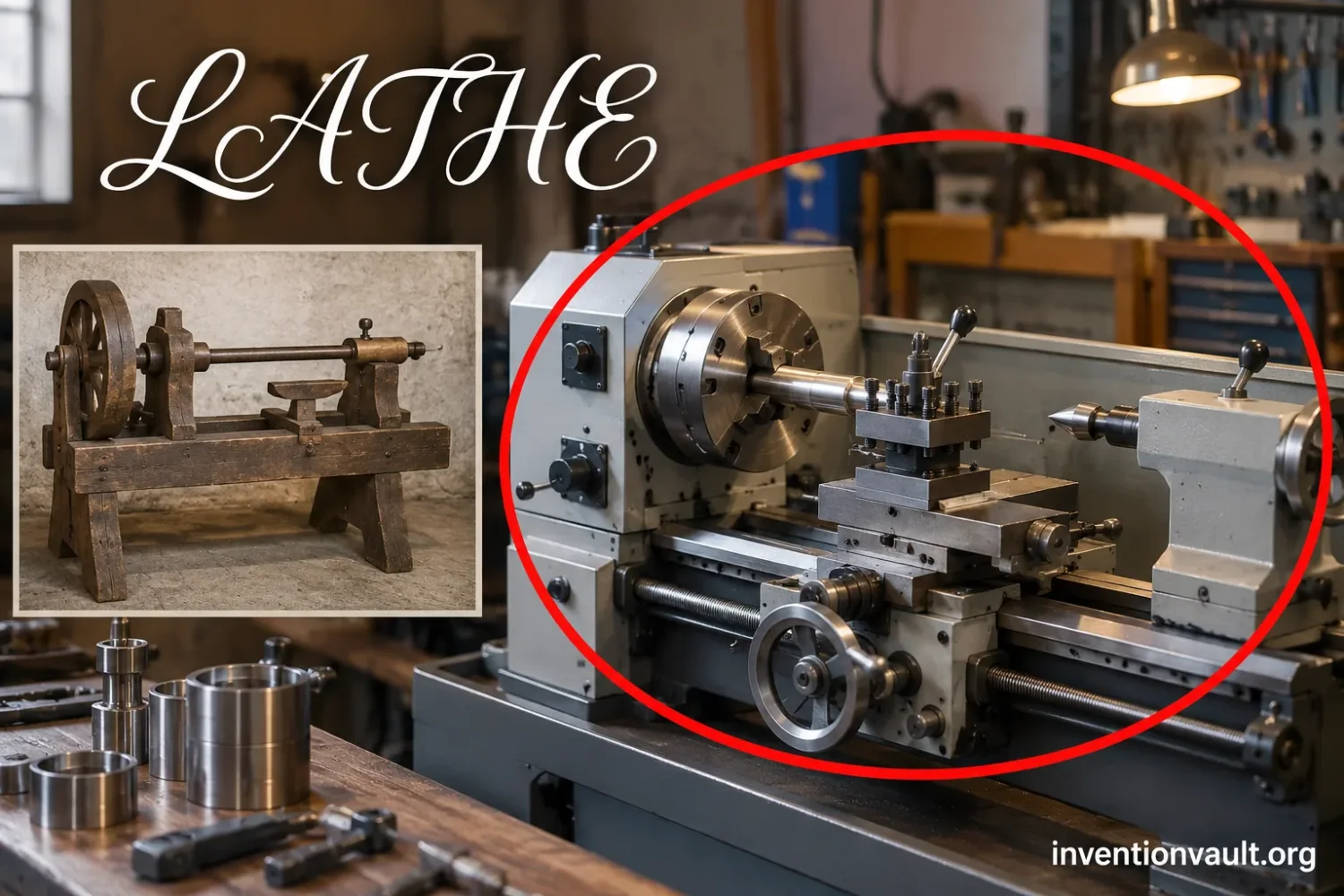
The defining action of a lathe is easy to state. The workpiece rotates around an axis, and a tool removes material as it contacts that rotating surface. Cylinders, tapers, grooves, shoulders, curved profiles, and screw threads can all be produced by controlling the geometry of that relative motion.
That basic idea does not require a motor, gears, a cast-iron bed, or even continuous rotation. An early lathe could be powered entirely by people. One person could turn the work with a cord while another controlled a cutting tool. The result was slower and more dependent on skill than later machines, but it already contained the defining relationship between rotating work and a shaping tool.
The Petosiris Tomb and the Earliest Famous Lathe Image
Cornell University Library catalogs a relief associated with the tomb of Petosiris, around 300 BCE, as the oldest known representation of a lathe. The drawing shows two seated workers. One uses a band to rotate an object held in a frame, while the other applies a tool to its surface.
The scene is valuable because it records the working principle directly. It is not an invention certificate. The device could have existed earlier, and the individual or community that first developed the method is unknown.
What Different Evidence Can Tell Us
- Ancient depictionShows that a turning method was in use by the date associated with the image, but does not identify when or where the method originated.
- Surviving machineAllows historians to inspect construction, materials, guides, feeds, gearing, and tool-control mechanisms directly.
- Patent recordDocuments a legal claim to a described machine or improvement. It does not prove that no related machine existed earlier elsewhere.
- Workshop adoptionShows whether a design moved beyond an isolated example and became useful for repeatable manufacturing.
How a Two-Person Early Lathe Worked
- Hold the work on an axisThe piece is supported so that it can rotate while remaining in a controlled position.
- Apply rotational motionA cord or band turns the workpiece. In a reciprocating arrangement, the work reverses direction as the cord is pulled back and forth.
- Bring in the cutting toolA second worker places a sharp tool against the rotating surface during the useful part of the motion.
- Repeat the cutSuccessive passes remove material until the required round or decorative form emerges.
The limitation is clear: both motion and accuracy depend heavily on people. A skilled turner can produce refined work, but the path of a hand-held cutter is not mechanically fixed to the axis of rotation.
Precision Depended on Controlling the Cutting Tool
Making the workpiece rotate was only part of the engineering problem. Metalworking demanded tighter control over the cutter itself. If the tool shifts, twists, or moves unevenly under cutting force, the finished diameter changes. If it cannot travel along a predictable straight path, producing the same geometry again becomes difficult.
Hand-Held Cutting
The operator supports and moves the cutter directly. Accuracy depends strongly on hand control, tool pressure, experience, and the ability to resist vibration and cutting forces.
Machine-Guided Cutting
The cutting tool is clamped to a rest or carriage whose permitted motion is defined by guides and screws. The machine itself determines much of the cutting path.
This change altered where precision came from. Instead of asking the operator to reproduce the same path by hand, a machine could constrain the cutter to a known direction. Straight guides could produce straight travel. A feed screw could turn rotary motion into measured linear movement. Gears could coordinate that movement with spindle rotation.
The Slide Rest Was an Idea Before Maudslay
The slide rest is often attached too neatly to Henry Maudslay’s name. Earlier designers had already explored mechanically supported and guided cutting tools. Andrey Nartov, working in Russia during the early eighteenth century, built elaborate copying lathes in which mechanical systems controlled the relationship between a pattern, a tool, and the rotating work.
A copying lathe attributed to Nartov and dated to 1721 survives in the Hermitage Museum. Such machines were largely associated with decorative and copying work rather than the general-purpose industrial turning later performed by engine lathes, but they demonstrate that guided tool movement was not new around 1800.
Nartov therefore belongs in the development history without being turned into another single-inventor answer. Mechanical rests and copying systems appeared in more than one workshop tradition, and their influence was not necessarily continuous from one inventor to the next.
Vaucanson’s 1751 Lathe Joined Rigidity With Guided Feed
Jacques de Vaucanson encountered a practical manufacturing problem in the French silk industry. Producing a moiré effect involved passing fabric between copper cylinders, and those cylinders needed to be turned with much more consistent geometry than a flexible wooden machine could easily provide.
His solution, built in 1751, survives in the Musée des Arts et Métiers. The museum describes a machine with an all-metal structure, a cutting tool fixed to a carriage, carriage movement controlled by a leadscrew, continuous manual rotation of the cylinder, and prismatic guides.
These details matter because they address different sources of error at once. The frame supports alignment. The guides restrict where the carriage can move. The screw produces controlled travel. The cutter is no longer floating freely in the operator’s hands.
Why an All-Metal Structure Changed the Cut
A cutting tool pushes against the workpiece as it removes material. That force also pushes back into the tool holder, carriage, supports, and bed. If the machine bends under the load, the cutter no longer follows the intended geometry.
Wood can make an effective lathe structure for many forms of turning, but heavy metal work exposes its limitations. Moisture can alter dimensions, joints can shift, and a lightly built frame may deflect or vibrate under load. A rigid metal structure can support heavier components while holding the main axes in a more stable relationship.
The engineering sequence is direct: greater stiffness helps preserve alignment; preserved alignment makes tool position more predictable; predictable tool position improves repeatability.
Vaucanson’s machine did not end the development of the lathe. It shows that several features later associated with industrial turning—metal construction, guided carriage motion, and screw feed—were already combined in a working machine decades before Maudslay’s best-known work.
Screw Cutting Required Rotation and Linear Travel to Stay Synchronized
A screw thread is a helix. Cutting one accurately requires more than moving a tool along a rotating cylinder. The cutter must advance by a controlled distance for every revolution of the workpiece.
Thread pitch is determined by the axial distance traveled during one revolution. If the work turns once while the cutting tool advances 2 millimeters, the resulting helix has a 2-millimeter pitch. Any error in the relationship between those two motions changes the thread.
Hand methods could produce usable screws, but repeatability was difficult. Even screws that looked similar could differ in pitch, profile, diameter, or depth. A screw and its matching nut might therefore have to remain a paired set rather than being freely exchangeable with parts from another batch.
How a Mechanical Screw-Cutting Lathe Controls Pitch
- The spindle turns the workpieceThe cylindrical blank rotates around its axis while the cutting tool is positioned at the required diameter.
- Gearing transfers rotationGears establish a chosen rotational relationship between the spindle or mandrel and the leadscrew.
- The leadscrew creates linear travelAs the leadscrew rotates, it moves the carriage along the bed at a rate determined by its own pitch and the gear ratio.
- The cutter follows a helixBecause workpiece rotation and carriage travel remain linked, the tool traces a controlled spiral path along the surface.
- Repeated passes deepen the threadThe cutter can return and make additional passes along the same helical path until the required thread form and depth are reached.
The mechanism converts a relationship that once depended heavily on a turner’s judgment into one set by machine geometry. Changing the gearing changes the rate of carriage travel relative to spindle rotation and therefore changes the thread pitch that can be cut.
David Wilkinson and the American Screw-Cutting Route
Precision machinery was developing on both sides of the Atlantic. In the United States, Rhode Island machinist David Wilkinson received a patent in 1798 for a machine for cutting screws.
Wilkinson worked in a manufacturing environment where the need for machine tools was immediate. The textile machinery associated with the early industrial development of Pawtucket required shafts, screws, fittings, repairs, and replacement components. Machine shops were not simply producing finished consumer objects; they were producing and maintaining the machinery used to manufacture other goods.
The National Park Service identifies Wilkinson’s screw-cutting lathe as one of his major inventions and links his machine-shop work to the growth of machinery production in the Blackstone River Valley. His 1798 patent gives the American screw-cutting story a documented milestone independent of the better-known British developments associated with Maudslay.
That does not require choosing Wilkinson or Maudslay as the single winner. Their work addressed the same broad manufacturing problem: how to make the cutter move predictably enough to reproduce accurate mechanical forms.
What Henry Maudslay Actually Added to Lathe Development
Henry Maudslay’s historical importance becomes clearer when his contribution is stated narrowly. He did not invent the basic lathe, and guided tool rests existed before his workshop. His preserved machines instead show how precise screw cutting became a practical machine-tool operation.
The Science Museum Group preserves an original Maudslay screw-cutting lathe made around 1800. It consists of two parallel triangular bars. Headstocks support the rotating work, while a slide rest carrying the cutting tool rides on the bars. A leadscrew positioned between them moves the slide rest, and change wheels connect that leadscrew to the lathe mandrel.
The tool holder includes a screw feed and a micrometer dial for adjusting depth of cut. The machine itself was hand-driven, which is an important reminder that precision and motorization are separate developments. A lathe does not need an electric motor—or even steam power—to embody controlled machine geometry.
| Feature on Maudslay’s c. 1800 lathe | Mechanical function | Why it mattered |
|---|---|---|
| Parallel triangular bars | Support and guide the machine’s major moving elements. | They help maintain a defined relationship between the work axis and tool travel. |
| Slide rest | Holds the cutting tool and constrains its movement. | The cutter follows machine-defined travel instead of unrestricted hand motion. |
| Leadscrew | Converts rotation into controlled carriage movement along the work. | Linear feed can be tied directly to workpiece rotation. |
| Change wheels | Set the rotational ratio between the mandrel and leadscrew. | Different ratios allow different thread pitches to be generated. |
| Micrometer dial and screw feed | Regulate the cutting tool’s position and depth of cut. | Successive passes can be adjusted in smaller, more controlled increments. |
The Science Museum Group describes this as the machine Maudslay used to pioneer the manufacture of highly accurate screw threads. The Henry Ford also preserves a Maudslay production lathe from about 1800 and reports that it could machine to an accuracy of several thousandths of an inch.
Those surviving objects explain why Maudslay remains central to the story. His importance rests on the quality, practicality, and influence of precision machine tools rather than a claim that no lathe existed before him.
Repeatable Threads and Standard Threads Are Different Achievements
Precision Is Not Standardization
A screw-cutting lathe can repeatedly make a chosen thread pitch without establishing which pitch, diameter, or thread form every other workshop should use. Manufacturing precision and industry-wide standardization are separate steps.
This distinction prevents another common compression of the history. Better lathes made it possible to reproduce threads more accurately, but different workshops could still use different thread forms and sizes.
Joseph Whitworth later proposed a common British screw-thread system in 1841, relating thread form and pitch to bolt diameter. That later standardization effort should not be moved backward and credited automatically to the first accurate screw-cutting machines.
The chain was longer: machine tools improved repeatability; measurement and gauges improved verification; agreed specifications then allowed separate workshops to target the same dimensions. Reliable interchangeability depends on all of those conditions, not on one lathe alone.
The Lathe Became a Machine for Making Machines
The lathe is often called the “mother of machine tools”. The useful part of that description is mechanical rather than ceremonial. Many machines contain components with rotational geometry, and a lathe is especially suited to producing them.
Typical machine components that can be turned include shafts, spindles, cylindrical bearing surfaces, threaded parts, pulleys, rollers, bushings, pins, and fitted shoulders. A shop with a capable lathe could therefore manufacture parts for pumps, textile machinery, engines, scientific instruments, and other machine tools.
This created a reinforcing manufacturing cycle. Better lathes produced more accurate machine components. Those components could be incorporated into more accurate machinery, which could then produce parts with tighter control.
That process should not be confused with the claim that the lathe single-handedly created interchangeable-part manufacturing. Interchangeability also depends on measurement, gauges, tolerances, stable processes, tooling, standards, inspection, and suitable production organization.
Lathe Invention Timeline
| Date or period | Documented development | What changed |
|---|---|---|
| Before c. 300 BCE | Turning techniques were already in use before the surviving Petosiris depiction. | The rotating-workpiece principle existed without a known individual inventor. |
| c. 300 BCE | Petosiris tomb scene provides a famous surviving visual record of manual lathe operation. | Two-person rotation and cutting are directly depicted. |
| Early 1700s | Mechanically guided copying lathes appear in European workshop traditions; Nartov is one documented designer. | Tool movement can be constrained and coordinated mechanically. |
| 1721 | A Nartov copying lathe from this period survives. | Geared, controlled tool motion is represented in a preserved early machine. |
| 1751 | Vaucanson builds his all-metal carriage lathe. | Rigid metal construction, guided cutting, screw feed, and prismatic guides are combined. |
| 1798 | David Wilkinson receives a U.S. patent for a machine for cutting screws. | Screw-cutting machinery acquires a clear American patent record. |
| c. 1800 | Maudslay develops highly accurate screw-cutting lathes. | Leadscrew, change-wheel gearing, guided tool travel, and fine adjustment support repeatable precision. |
| 1800s | Heavier engine lathes, mechanical feeds, broader gearing, and powered shop systems spread. | The lathe becomes a general industrial metalworking machine. |
| 1841 | Joseph Whitworth introduces a common British screw-thread system. | Thread standardization begins solving a problem that accurate screw cutting alone could not solve. |
| 1950s onward | Numerical control, followed by computer numerical control, is applied to machine tools. | Programmed commands and servo motion take over many positioning tasks formerly controlled mechanically or by hand. |
From the Engine Lathe to NC and CNC Turning
Nineteenth-century engine lathes retained the same basic workpiece-and-tool relationship while adding heavier beds, stronger headstocks, wider speed ranges, mechanical feeds, gearing, and shop power. The machine became capable of more operations without changing the physical definition of turning.
The next major control shift came with numerical control. NIST records the development of the first generation of NC machine tools in the 1950s. Instead of requiring every axis movement to come directly from handwheels, mechanical templates, or dedicated mechanisms, machine motion could be commanded by encoded instructions.
Computer numerical control extended that idea. A modern CNC lathe can coordinate several axes, control spindle speed and feed, repeat stored tool paths, manage tool changes, and machine complex parts through programmed sequences.
Yet an ancient turner and a CNC turning center still share one recognizable geometric rule: the workpiece rotates while controlled relative tool movement creates the surface. What changed most dramatically was the way that movement became controlled, measured, repeated, and automated.
Who Invented the Lathe?
If “lathe” means the basic method of shaping a rotating workpiece, no known person can be credited as its inventor. The technique is older than the surviving records that describe it.
If the question concerns early mechanically guided tool motion, Nartov belongs among the documented eighteenth-century contributors, but the evidence does not justify treating him as the sole originator of every later slide-rest design.
If the question concerns a preserved all-metal machine combining rigid construction with guided carriage travel, Jacques de Vaucanson’s 1751 lathe is an especially clear milestone.
If the question concerns American screw-cutting machinery, David Wilkinson’s 1798 patent provides a documented contribution during the same broad period in which precision machine tools were developing in Britain and Europe.
If the question concerns the highly accurate screw-cutting lathe that became closely associated with industrial precision, Henry Maudslay’s work around 1800 deserves its well-established place. His achievement was not inventing rotation on a lathe. It was helping make the relationship between rotation, guided tool motion, feed, and measurement accurate enough to support repeatable engineering work.
The invention of the lathe is therefore a rare case where assigning one inventor makes the history less accurate. Its present form emerged as craftsmen and engineers transferred more of the work—from rotating the piece, to guiding the cutter, to setting feed, to coordinating axes—from human judgment into the geometry and control systems of the machine itself.
References Used for This Article
- Cornell University Library Digital Collections — Oldest Known Lathe on the Tomb of Petosiris. Used for the c. 300 BCE Petosiris depiction and its cataloged description of two-person lathe operation.
- Linda Hall Library — Andrey Nartov. Used for Nartov’s early copying-lathe work, mechanical tool guidance, and the surviving 1721 machine.
- Musée des Arts et Métiers — Tour à charioter de Vaucanson. Used for the 1751 date, moiré-silk manufacturing problem, all-metal construction, carriage, leadscrew, and prismatic guides.
- Science Museum Group — Henry Maudslay’s Original Screw-Cutting Lathe, c. 1800. Used for the preserved machine’s slide rest, triangular bars, leadscrew, change wheels, micrometer dial, and hand-driven operation.
- Science Museum Group — Model of Screw-Cutting Lathe with Associated Tools. Used to clarify the mechanical relationship between gearing, leadscrew motion, the sliding saddle, and repeated thread-cutting passes.
- The Henry Ford — Maudslay Production Lathe, circa 1800. Used for the preserved production lathe and its reported machining accuracy of several thousandths of an inch.
- U.S. National Park Service — David Wilkinson and the Rise of American Industry. Used for Wilkinson’s machine-shop context and his role in early American machinery production.
- ASME — David Wilkinson. Used for Wilkinson’s 1798 screw-cutting-lathe patent and its engineering history.
- ASME — The United States Standard Screw Threads. Used for the distinction between accurate screw cutting and later thread standardization, including Whitworth’s 1841 system.
- National Institute of Standards and Technology — STEP-Compliant NC Research. Used for the development of first-generation numerical-control machine tools in the 1950s and the later CNC control lineage.