| Field | Details |
|---|---|
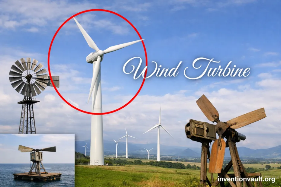
| Invention Name | Wind Turbine (electricity-generating wind machine) |
| Primary Purpose | Convert the kinetic energy of moving air into electrical energy via a rotating generator. |
| Energy Conversion Chain | Wind → rotor torque → drivetrain or direct drive → generator → power electronics → grid or local loads. |
| Core Aerodynamic Mechanism | Mostly lift-based blades (airfoil shapes); some variants use drag-based rotors. |
| Most Common Architecture | Horizontal-axis, three-bladed, upwind rotor on a tall tower. |
| Earliest Documented Wind-Generated Electric Lighting | James Blyth’s wind-powered system lighting a cottage in Marykirk, Scotland (between 1885 and 1887). |
| Notable Early Wind-Electric Machine | Charles F. Brush built and operated a wind turbine in Cleveland, Ohio in the 1880s (often cited as about 12 kW). |
| Early Experimental Milestone | Poul la Cour’s electricity-producing wind installation at Askov, Denmark (1891), plus systematic rotor experiments. |
| Key Theoretical Limit | Betz Limit: an ideal rotor cannot capture more than ~59% of wind power through its swept area. |
| Offshore Milestone | Technology development for offshore wind commonly points to the 1991 Vindeby installation (Denmark). |
| Standard Family Used Worldwide | IEC 61400 series for design and testing; IEC 61400-1 defines core design requirements. |
| Typical Scale | Ranges from small machines for buildings or farms to multi-megawatt turbines in utility wind farms. |
| Typical Design Life | Commonly planned around 20–25 years, depending on site conditions and design class. |
| Key Safety And Protection Features | Overspeed control (pitch or stall), braking systems, lightning protection, monitoring sensors, and shutdown logic. |
| End-Of-Life Pathways | Refurbishment, repowering, component reuse, metal recycling; blade recycling options are expanding as materials and methods improve. |
A wind turbine is an invention built around a simple idea: let moving air do useful work, then convert that motion into electricity with modern engineering. Its impact is practical and visible—turbines can supply power close to where people live and work, and they scale from compact machines to large wind farms.
- What The Machine Does
- Why Turbines Look So Tall
- What A Wind Turbine Is
- Key Parts and What They Do
- Inside The Nacelle
- How Wind Turns Into Electricity
- A Useful Rule Of Thumb
- Design Choices That Shape Performance
- Rotor Diameter And Swept Area
- Pitch Control And Stall Regulation
- Yaw Alignment And Turbulence
- Main Turbine Designs and Variations
- Horizontal-Axis Wind Turbines
- Vertical-Axis Wind Turbines
- A Brief Development Timeline
- Onshore and Offshore Wind Turbines
- Measuring Output In The Real World
- Terms That Clarify Performance
- Materials, Lifespan, and Maintenance
- What Usually Gets Monitored
- Standards and Certification
- Why Standards Matter
- Common Questions People Ask
- References Used for This Article
What The Machine Does
- Captures wind energy with a rotor sweeping a large area.
- Turns that torque into stable electrical output using generator and power electronics.
- Protects itself with sensing, control, and shutdown systems when conditions become extreme.
Why Turbines Look So Tall
- Wind speed generally rises with height, which boosts available power.
- A taller tower helps the rotor see cleaner flow above local turbulence.
- More swept area means more potential energy capture.
What A Wind Turbine Is
A wind turbine is a rotating energy converter. Most modern machines use airfoil-shaped blades that generate lift, producing torque on a central shaft. That rotation drives a generator, and the output is conditioned so it can be delivered as reliable electrical power.
While historic windmills often powered mechanical tasks, today’s turbines are designed around electrical generation, grid compatibility, and long-term structural durability. The core physics stays the same, but materials, controls, and standards have transformed performance and reliability.
Key Parts and What They Do
- Blades: Capture energy; their shape and stiffness control efficiency and loads.
- Hub: Connects blades; often houses pitch mechanisms at each blade root.
- Pitch System: Rotates blades to regulate power and reduce loads in strong winds.
- Main Shaft: Carries torque from rotor to drivetrain.
- Gearbox (if present): Steps up rotational speed for the generator.
- Generator: Converts mechanical rotation into electrical power.
- Power Electronics: Shape voltage and frequency for stable output.
- Yaw System: Turns the nacelle so the rotor faces the wind.
- Nacelle: Protective housing for major components and sensors.
- Tower: Lifts the rotor into stronger winds; also carries cables downward.
- Foundation: Transfers loads into soil or seabed; offshore designs vary by depth.
Inside The Nacelle
Think of the nacelle as the turbine’s protected “engine room.” It houses critical equipment, plus sensors that inform control decisions every second.
- Anemometer and wind vane for wind measurement
- Controllers, safety systems, and communication hardware
- Brakes and emergency shutdown components
How Wind Turns Into Electricity
Wind turbines do not “create” energy. They redirect a stream of moving air, extracting part of its kinetic energy while letting the air continue downstream.
- The rotor faces the wind using the yaw system.
- Air flows over the blades, producing lift and rotor torque.
- The drivetrain spins the generator (with or without a gearbox).
- Power electronics condition the output for stable delivery.
- Transformers and cables carry electricity to local loads or the grid.
A Useful Rule Of Thumb
The power available in the wind rises very fast with speed: it scales with wind speed cubed. That is why siting, hub height, and rotor size matter so much.
P_available ∝ ρ × A × V³
Where:
ρ = air density, A = rotor swept area, V = wind speed
Even in ideal conditions, there is a hard ceiling on extraction. The well-known Betz Limit shows an ideal rotor cannot capture more than about 59% of the wind power passing through its swept area.
Design Choices That Shape Performance
Rotor Diameter And Swept Area
Rotor diameter is a defining feature because it sets the swept area. A larger swept area gives the turbine more wind to work with, though structural loads and material demands also rise.
Pitch Control And Stall Regulation
Modern utility turbines usually use blade pitch control to regulate power, reduce fatigue loads, and respond smoothly to gusts. Some designs use stall behavior in the blade aerodynamics as a simpler form of regulation, often paired with other protective controls.
| Design Choice | What It Prioritizes | Typical Trade-Off |
|---|---|---|
| Pitch-Regulated | Fine control of power and loads across changing winds | More actuators, sensors, and control complexity |
| Stall-Regulated | Simpler aerodynamic self-limiting behavior | Less flexible control under rapidly changing conditions |
| Geared Drivetrain | Compact generator speed range and familiar architecture | More rotating parts and lubrication needs |
| Direct Drive | Fewer mechanical stages between rotor and generator | Larger generator and different materials/design constraints |
Yaw Alignment And Turbulence
A turbine produces more energy when it is aligned with the wind. Yaw systems rotate the nacelle to keep the rotor facing into the flow, while control software balances energy capture against fatigue from constant small adjustments.
Main Turbine Designs and Variations
Horizontal-Axis Wind Turbines
The familiar three-bladed design is a horizontal-axis turbine. It usually operates upwind (rotor in front of the tower), which helps reduce flow disturbance from the tower and supports stable control.
- Upwind vs. downwind configurations
- Fixed-speed vs. variable-speed operation (often with power electronics)
- Geared vs. direct-drive drivetrains
Vertical-Axis Wind Turbines
Vertical-axis turbines rotate around a vertical shaft. Some use lift-based rotors (often referred to as Darrieus-type), while others use drag-based concepts (often referred to as Savonius-type). They can accept wind from many directions, though their engineering trade-offs differ from the dominant horizontal-axis approach.
| Design Family | Strengths | Typical Challenges |
|---|---|---|
| Horizontal-Axis | High efficiency at scale; mature supply chain; strong standards support | Needs yaw alignment; tall structures increase logistics complexity |
| Vertical-Axis | Accepts wind from many directions; potential for compact layouts | Different load patterns; fewer large-scale reference designs |
A Brief Development Timeline
Wind turbines evolved through practical experimentation, theoretical advances, and large-scale engineering. The milestones below highlight well-documented steps that shaped the modern machine.
| Period | Milestone | Why It Matters |
|---|---|---|
| 1885–1887 | James Blyth’s wind-powered electricity for lighting | Early proof that wind can generate usable electric power for real needs. |
| 1880s | Charles F. Brush operates a wind turbine in Cleveland | Shows a larger, engineered wind-electric machine in practical operation. |
| 1891 | Poul la Cour builds an electricity-producing wind installation in Askov | Links wind electricity with systematic experimentation on rotor concepts. |
| Early 1900s | Theory of aerodynamic conversion matures | Establishes clear limits and design targets, including the Betz Limit. |
| 1991 | Vindeby installed offshore in Denmark | Marks a recognized starting point for modern offshore wind development. |
| Late 20th Century | Three-bladed horizontal-axis designs become dominant | Standardizes the architecture most widely used in large wind farms. |
Onshore and Offshore Wind Turbines
Onshore turbines are built on land, where access and maintenance are generally simpler. Offshore turbines operate at sea, where wind resources can be strong and steady, but the environment demands marine-grade engineering.
| Feature | Onshore | Offshore |
|---|---|---|
| Foundation | Concrete/steel foundations in soil or rock | Fixed-bottom or floating platforms, depending on depth |
| Corrosion Exposure | Lower | Higher (salt spray, humidity, marine conditions) |
| Access | Road-based access for crews and cranes | Vessels and specialized logistics for installation and service |
| Typical Layout Drivers | Land availability, setbacks, terrain, local wind | Water depth, seabed conditions, waves, port proximity |
Measuring Output In The Real World
A turbine’s rated power is a reference point, not a promise for every moment. Real output depends on the wind at hub height, turbulence, air density, and how the machine is controlled to protect components.
Terms That Clarify Performance
- Power curve: Output as a function of wind speed for a given turbine model.
- Capacity factor: Average output divided by rated output over time.
- Availability: Share of time the turbine is able to operate when wind is present.
- Wake effects: Energy loss and turbulence behind turbines that influence wind farm layout.
Materials, Lifespan, and Maintenance
Utility-scale turbines combine durable metals and advanced composites. Towers are typically steel, while blades often use fiberglass composites, sometimes reinforced with carbon fiber for stiffness and weight control.
Over a typical service life, operators focus on condition monitoring and planned maintenance to manage wear, lightning events, and leading-edge erosion on blades. Modern sensors, inspection routines, and data systems help keep reliability high without treating the turbine as a “black box.”
What Usually Gets Monitored
- Vibration and temperature indicators for rotating machinery
- Blade pitch behavior and actuator health
- Electrical quality, converter temperatures, and insulation indicators
- Structural loads and fatigue signals in key components
Standards and Certification
Wind turbines are engineered to defined design conditions and safety expectations. The IEC 61400 standards family provides widely used requirements and test methods, supporting consistent design, evaluation, and certification practices.
Why Standards Matter
- They define consistent design load cases and environmental assumptions.
- They support repeatable testing for performance and safety.
- They help manufacturers and operators align on documentation and verification.
Common Questions People Ask
Do wind turbines work when the wind is light?
They start producing once wind reaches the turbine’s operating range, then output climbs as wind strengthens, guided by control limits that protect the machine.
Why do turbines sometimes stop even when it is windy?
Temporary stops can be part of normal protection logic, maintenance windows, or grid requirements, ensuring the turbine remains within safe operating limits.
What determines the “right” turbine size for a site?
Key factors include local wind conditions, available space, electrical connection limits, and structural design constraints, all weighed against the project’s goals.
Is one turbine design best for every situation?
Different sites reward different choices—rotor size, tower height, and control strategy are tuned to match wind resource and operating constraints.
References Used for This Article
- U.S. Department of Energy — History of U.S. Wind Energy: A government overview of key historical developments in wind power and wind turbine technology.
- U.S. Department of Energy — From 1970s Pioneers to Today’s Wind Industry: Aerospace Researchers Championed Wind Energy: Notes early U.S. interest in wind-generated electricity, including Charles Brush’s 1880s turbine.
- University of Strathclyde Archives & Special Collections — Papers of James Blyth: Archival description documenting Blyth’s wind-powered electricity work in the 1880s.
- University of Houston, The Engines of Our Ingenuity — Old Wind and Electricity: A university engineering resource describing early wind-electric machines, including Brush.
- SpringerLink — Strom aus Wind – Die ersten Versuche: A scholarly chapter PDF describing early wind-electric experimentation, including Poul la Cour’s 1891 installation.
- Penn State AERSP 583 — 2a.2 The Actuator Disk Model: Explains rotor power coefficients and the Betz Limit as a fundamental theoretical bound.
- DTU Research Database — Offshore Wind Farms: An academic overview noting offshore wind’s early development, including the 1991 Vindeby installation.
- IEC Webstore — IEC 61400-1:2019 Wind energy generation systems – Part 1: Design requirements: Standard description summarizing essential design requirements used in wind turbine engineering and certification.