Vacuum Tube Profile
| Primary Name | Vacuum Tube (electron tube) |
| Common Alternate Term | Thermionic valve (widely used in the UK) |
| Core Idea | Control the flow of electrons through a high vacuum using electric fields |
| Key Early Milestones | 1883 Edison effect observed; 1904 Fleming diode; 1906 de Forest triode (Audion) |
| What It Made Possible | Rectification, amplification, oscillation, switching, display, and high-frequency power generation |
| Main Working Parts | Cathode, anode (plate), one or more grids, glass/ceramic envelope, getter |
| Typical Heater Supply | Common receiving tubes use 6.3 V or 12.6 V heaters; current varies widely by tube family |
| Typical Plate Voltage Range | From tens of volts (small-signal stages) to kilovolts (power, display, and specialized tubes) |
| Vacuum Quality | Designed for very low gas pressure; performance depends on clean internal surfaces and effective getters |
| Where You Still See Them | Audio amplification, RF transmitters, specialized lab gear, magnetrons in microwave ovens, X-ray tubes, photomultipliers |
| Common Limits | Warm-up time, heat, size, higher power draw, sensitivity to vibration (microphonics) |
| Safety Note | High voltages and hot surfaces are typical in tube equipment |
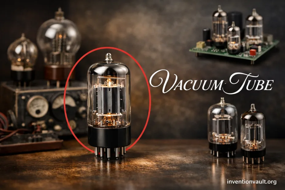
A vacuum tube is an electronic device that guides electron flow inside a sealed envelope with very little gas. By shaping electric fields with carefully placed electrodes, a vacuum tube can amplify signals, convert AC to DC, generate oscillations, or switch currents with surprising authority.
- Vacuum Tube Profile
- Why This Invention Mattered
- Names You May See
- What a Vacuum Tube Is
- Core Parts and Roles
- The Parts You Can Name
- What Each Part Changes
- How It Works in Practice
- A Simple Internal Map
- Key Milestones
- Major Tube Types
- Diode Tubes
- Triode Tubes
- Tetrode and Pentode Tubes
- Power and Transmitting Tubes
- Microwave Tubes
- Display and Sensor Tubes
- Why the Vacuum Matters
- Safety Notes Around Tube Equipment
- Materials That Shape Performance
- Understanding Key Tube Specifications
- Common Terms
- What Those Numbers Reveal
- Where Vacuum Tubes Still Appear Today
- Common Performance Traits
- A Small Glossary for Tube Reading
- References Used for This Article
Why This Invention Mattered
Vacuum tube technology turned weak electrical signals into usable power long before the transistor era. It enabled early long-distance voice amplification, reliable radio reception, and the first generations of electronic computing. Even today, certain tasks still favor electron tubes because a vacuum environment can handle high voltages and strong RF power in a compact active device.
Names You May See
- Vacuum tube (general term)
- Thermionic valve (common in historical British texts)
- Electron tube (broad technical category)
- Valve (often used for radio-era schematics)
What a Vacuum Tube Is
A vacuum tube is built around one simple physical fact: a heated surface can release electrons into space. Inside a sealed vacuum, those electrons travel freely until an electric field pulls them toward a positive electrode. Add one or more grids between the electrodes, and a small control signal can steer a much larger current. That single trick—electron control—is why the vacuum tube became a foundation of early electronics.
Core Parts and Roles
The Parts You Can Name
- Heater / filament: warms the cathode (or acts as cathode in some designs).
- Cathode: emits electrons through thermionic emission.
- Anode (plate): attracts electrons; collects the current.
- Grid: a wire structure that controls current with a small voltage.
- Envelope: glass or ceramic seal that maintains vacuum.
- Getter: reactive material that helps keep residual gases low over time.
What Each Part Changes
In a vacuum tube, the cathode sets the supply of electrons, while the plate voltage sets how strongly they are pulled across the gap. The control grid is the steering wheel: a tiny change at the grid can cause a much larger change at the plate. Extra grids (screen and suppressor) reduce unwanted effects and improve stability in high-gain or high-power designs.
The getter matters more than most people expect. A clean vacuum reduces random ion collisions, protects the cathode surface, and keeps the tube’s characteristics consistent over years of use.
How It Works in Practice
- Heat brings the cathode to a temperature where electrons can leave its surface.
- A positive anode (plate) voltage pulls those electrons through the vacuum gap.
- A grid between cathode and plate shapes the electric field, throttling electron flow with a small input signal.
- The changing plate current creates an amplified voltage across a load, making the vacuum tube useful as a gain device.
A Simple Internal Map
Cathode (emits e-) → Grid (controls) → Plate/Anode (collects)That short path is why vacuum tubes can feel so direct in certain circuits: fewer solid-state junctions, and a field-controlled current in open space. The behavior is still rich, because electrons form a space charge cloud near the cathode and respond dynamically to grid voltage.
Key Milestones
| Year | Milestone | Why It Changed Things |
|---|---|---|
| 1883 | Edison effect observed | Showed that heated electrodes could move charge in a near-vacuum environment |
| 1904 | Fleming diode (thermionic valve) | Practical rectifier for turning AC into DC |
| 1906 | de Forest triode (Audion) | Added a control grid, enabling amplification |
| 1910s | Higher-vacuum improvements and better cathodes | Made vacuum tubes more stable, predictable, and higher gain |
| 1920s | Multi-grid tubes mature (screen-grid, pentode) | Reduced distortion and improved high-frequency performance |
| 1930s–1950s | Power and microwave tube families expand | Enabled strong RF output, industrial heating, and specialized instrumentation |
| Late 20th century–today | Transistors dominate, tubes remain specialized | Tubes persist where high voltage, linearity, or extreme RF power is prized |
Major Tube Types
Diode Tubes
A diode vacuum tube has two electrodes: cathode and anode. Current flows easily in one direction because electrons leave the hot cathode and are attracted to the positive plate. Reverse the polarity and the tube blocks current, which made early power supplies far cleaner and more reliable than many mechanical alternatives. For readers exploring classic circuits, the rectifier tube is the simplest starting point.
Triode Tubes
The triode adds a control grid between cathode and plate. A small grid-voltage change can cause a large change in plate current, which is why the triode vacuum tube became a classic for audio and radio gain stages. Triodes are often praised for smooth overload behavior, though real performance depends on the tube type, circuit design, and operating point. In plain terms, the grid gives the vacuum tube its “amplifier personality.”
Tetrode and Pentode Tubes
Once engineers pushed triodes to higher frequencies and power, new side effects appeared. The tetrode adds a screen grid to reduce the influence of plate voltage on the control grid. The pentode adds another grid (often a suppressor) to control secondary emission from the plate. These multi-grid designs improved gain and stability, and they often delivered stronger output per watt of heater power. The tradeoff is complexity: more electrodes mean more ways for a vacuum tube to exhibit subtle behavior, including noise and vibration sensitivity.
| Type | Electrodes | Typical Strength | Common Use |
|---|---|---|---|
| Diode | Cathode, plate | Rectification | Power supplies, detectors |
| Triode | Cathode, grid, plate | Linear gain | Audio/RF amplification |
| Tetrode | Adds screen grid | Higher gain | RF stages, power output |
| Pentode | Adds suppressor grid | Stability | Audio power, RF amplification |
Power and Transmitting Tubes
A power vacuum tube is engineered for heat handling and high voltage, not just gain. Larger plates dissipate more energy, robust cathodes emit more current, and the envelope may use ceramic or forced-air cooling in extreme cases. In broadcasting and industrial RF systems, electron tubes still appear because they can deliver strong RF output with grace under high voltage. This is less about nostalgia and more about physics: high electric fields inside a vacuum can be managed with the right geometry and materials.
Microwave Tubes
At microwave frequencies, familiar small-signal tube structures stop behaving nicely. Specialized vacuum tube families evolved for that region: the magnetron (a high-power oscillator used in microwave ovens), the klystron (used for high-frequency amplification), and the traveling-wave tube (valued for wide bandwidth). These devices are still chosen in certain equipment where frequency and output power meet in a demanding way.
Display and Sensor Tubes
Not every vacuum tube is an amplifier. The cathode-ray tube (CRT) steers an electron beam onto a phosphor screen, creating images in classic televisions and oscilloscopes. Photomultiplier tubes use a vacuum structure to multiply tiny light-triggered electron signals into measurable current. Vacuum fluorescent displays also belong to the wider electron tube family, combining emissive cathodes with phosphors for bright readouts. Each of these relies on the same foundation: controlled electrons moving through open space.
Why the Vacuum Matters
A vacuum tube works best when stray gas molecules are scarce. Gas collisions can scatter electrons, generate ions, and shift operating points in annoying ways. A cleaner internal environment improves stability, reduces random noise, and protects the emitting surface of the cathode. If you’ve ever seen a shiny silvery patch inside a tube, you’ve likely noticed the getter deposit—one quiet reason vacuum tubes can stay consistent for long periods.
Safety Notes Around Tube Equipment
Many vacuum tube circuits involve high voltage and components that run hot. Even small devices can store energy in capacitors. This article stays focused on historical and technical understanding, yet it’s worth remembering that tube hardware should be treated with serious respect.
Materials That Shape Performance
The performance of a vacuum tube is tied to its materials. Cathodes may use oxide coatings for efficient emission, while some high-power designs rely on more rugged emitter surfaces. Plates are often nickel-based and shaped to radiate heat well. Internals use metals like tungsten and molybdenum where strength at temperature matters. Even the envelope choice matters: glass is common in receiving tubes, while ceramic packages appear when high frequency and thermal stability dominate. The tiny details—surface finish, spacing, cleanliness—set the tube’s noise floor and long-term consistency.
Understanding Key Tube Specifications
Common Terms
- Plate voltage: the anode potential that attracts electrons.
- Plate dissipation: how much heat the plate can safely shed.
- Transconductance (gm): how strongly grid voltage changes plate current.
- Amplification factor (μ): a triode’s gain-related constant.
- Heater current: power demand of the cathode heating system.
What Those Numbers Reveal
Two tubes with the same pinout can feel totally different because a vacuum tube is not just a “part,” it’s a set of interacting fields and surfaces. Higher transconductance can mean stronger gain, yet it can also make a stage more sensitive to layout and noise. Plate dissipation tells you how hard a tube can be pushed thermally. Heater ratings hint at size and emission capability. A good spec sheet is a snapshot of the tube’s operating envelope, not a promise of identical behavior in every circuit.
One more nuance: vacuum tubes are physical devices. Small differences in electrode spacing and internal alignment can lead to slight unit-to-unit variation, even within the same model. That human, mechanical reality is part of the technology’s history—and part of its charm, some would say.
Where Vacuum Tubes Still Appear Today
Modern electronics is largely solid-state, yet vacuum tubes still show up in places where they remain practical, distinctive, or difficult to replace. Some audio amplifiers use triodes or pentodes for their operating style. High-power RF transmitters may use specialized electron tubes because they can operate at high voltage with robust RF output. Everyday kitchens use a magnetron to generate microwave energy inside an oven. Medical and scientific equipment still relies on vacuum-based devices such as X-ray tubes and photomultipliers in certain measurement roles.
| Application Area | Typical Tube Family | Why It’s Used |
|---|---|---|
| Audio amplification | Triodes, pentodes | Voltage gain and distinctive overload behavior |
| Microwave ovens | Magnetron | Efficient high-frequency power generation |
| RF transmission | Klystrons, TWTs, power tetrodes | High voltage handling and strong RF output |
| Test and measurement | Specialized amplifier and display tubes | Stable performance in certain niche instruments |
| Imaging and detection | X-ray tubes, photomultipliers | Sensitive detection and controlled electron acceleration |
Common Performance Traits
- Warm-up time: emission rises as the cathode reaches operating temperature, so behavior can change during the first minute or two.
- Microphonics: some tubes convert vibration into small signal changes because internal elements can move slightly.
- Heat management: dissipation limits define safe operation and long-term stability.
- Finite cathode life: emission can decline gradually after long service.
- Voltage headroom: many tube circuits are comfortable at higher voltages than typical small-signal transistor stages.
These traits are not “good” or “bad” in isolation. They are the natural footprint of a vacuum tube doing its job: moving electrons through a controlled field inside a sealed vacuum. Engineers learned to design around them, and entire eras of dependable electronics were built on that understanding.
A Small Glossary for Tube Reading
Cathode: the electron-emitting electrode, often heated indirectly. Anode (plate): the positive collector of electrons. Grid: a control structure that shapes the electric field; in multi-grid tubes this includes a screen and sometimes a suppressor. Space charge: the cloud of electrons near the cathode that influences current flow. Getter: material that maintains vacuum quality by binding residual gases over time.
References Used for This Article
- Library of Congress — Lee De Forest Papers [finding aid]. Manuscript Division, Library of Congress.: Primary archival description of De Forest’s work and materials related to the Audion/triode era.
- IEEE Engineering and Technology History Wiki — Milestones: Fleming Valve, 1904: Documents the diode’s role as a practical rectifier and a key step toward amplification.
- IEEE Engineering and Technology History Wiki — Milestones: Development of the Cavity Magnetron, 1939–1941: Summarizes why cavity magnetrons enabled compact high-power microwave generation and radar-scale impact.
- Encyclopaedia Britannica — Thermionic emission | Thermionic Emission, Vacuum Tubes, Electron Flow: Explains thermionic emission as the foundational electron source for classic electron tubes.
- Encyclopaedia Britannica — Cathode-ray tube (CRT): Provides a concise technical description of CRTs as electron-beam vacuum devices for imaging.
- NASA Technical Reports Server (NTRS) — Development Program for 35 Watt Traveling-Wave Tube Space Amplifier (Final Report): Details a real TWTA design program and the engineering constraints of high-frequency tube amplifiers.
- SLAC National Accelerator Laboratory — Just what is a klystron?: Introduces klystrons as microwave generators used for extremely high-power accelerator RF systems.
- University of Chicago (PSEC) — Photomultiplier Tubes: Basics and Applications: Covers PMT operating principles and why vacuum electron multiplication enables extreme low-light sensitivity.
- University of Chicago (PSEC) — Getter Materials: Describes how getters capture residual gases to preserve vacuum quality and long-term tube stability.