| Detail | Information |
|---|---|
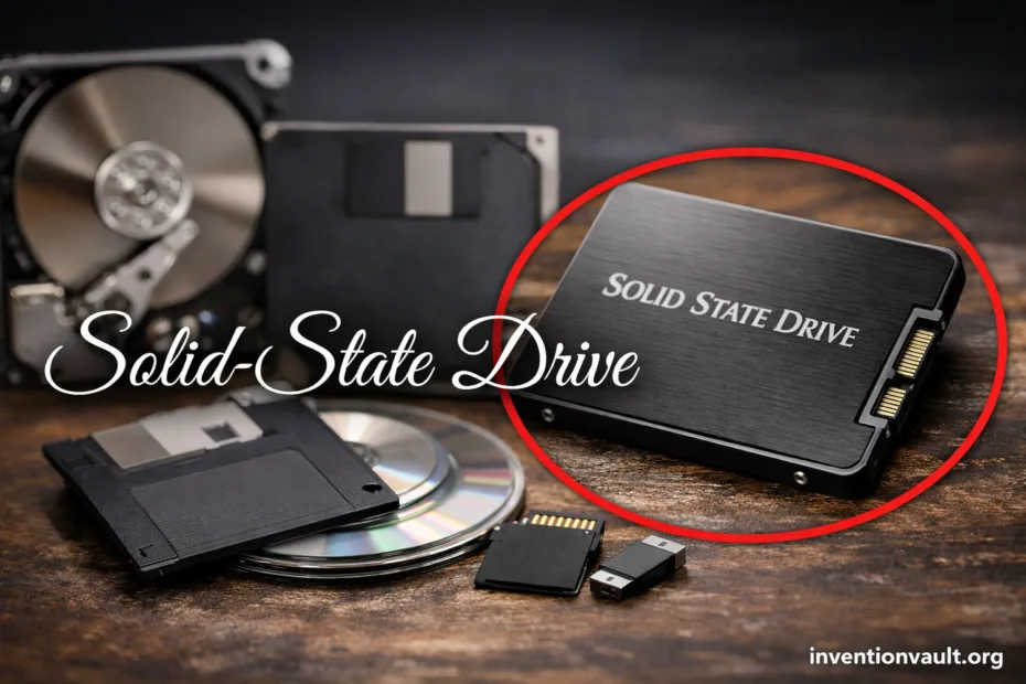
| Invention Name | Solid-State Drive (SSD) — a storage drive built from solid electronic memory rather than moving parts. |
| Core Breakthrough | Semiconductor-based mass storage with very low latency and improved mechanical resilience. |
| Early Commercial Milestone | StorageTek STC 4305 (1978) — an enterprise solid-state disk storing 45 MB at roughly $400,000, using semiconductor memory with backup support. |
| Flash Memory Pioneer | Fujio Masuoka (Toshiba) — developed key flash concepts in the early 1980s, publicly introducing NOR flash in 1984 and advancing NAND flash later in the decade. |
| Flash SSD Turning Point | SunDisk (founded 1988 by Eli Harari and partners) built a prototype flash SSD module for IBM in 1991, pairing a flash array with an intelligent controller. |
| Why It Mattered | Faster access, lower power use, and higher shock tolerance than rotating disks, enabling thin laptops and responsive systems. |
| Dominant Memory Type Today | NAND flash (now commonly 3D-stacked) managed by a controller with strong error correction. |
| Common Interfaces | SATA for broad compatibility and NVMe over PCIe for high parallel throughput and low protocol overhead. |
| Key Engineering Ideas | Wear leveling, garbage collection, over-provisioning, and host hints such as TRIM. |
| Where SSDs Show Up | Laptops, desktops, game consoles, servers, cameras, and external drives—anywhere quick access and reliable storage matter. |
Solid-state drives turned storage into a quiet, fast electronics problem. That shift wasn’t just about headline speeds; it made everyday computing feel snappyer because small requests finish quickly and consistently. Behind the scenes, a SSD controller coordinates billions of cells so your data stays safe and accessible.
- What a Solid-State Drive Is
- Why the Term “Solid-State” Matters
- How an SSD Stores Data
- Pages, Blocks, and Erase Rules
- Why Flash Wears Out
- Main Parts Inside an SSD
- SSD Families and Variations
- Interfaces: SATA and NVMe
- Form Factors: Where an SSD Fits
- NAND Types: SLC, TLC, and QLC
- Performance Numbers That Matter
- Core Metrics
- Typical Interface Ceilings
- Endurance, Reliability, and Data Safety
- What Protects Data on the Drive
- Why Free Space Changes Behavior
- The Host Side: TRIM and Modern Storage Stacks
- A Short, Clear History of SSD Development
- Compatibility Signals You Can Read at a Glance
- Common SSD Terms You Will See on Spec Sheets
- References Used for This Article
What a Solid-State Drive Is
An SSD stores data using NAND flash, a form of non-volatile memory that keeps information without power. With no spinning parts, an SSD delivers low latency and predictable access, even when the device is moved or used in tight spaces.
Why the Term “Solid-State” Matters
“Solid-state” highlights that data moves through solid electronic components rather than mechanical motion. That difference enables near-instant seeks and stronger shock resistance, while also reducing vibration, noise, and wasted energy.
How an SSD Stores Data
In a flash SSD, data lives in NAND cells that store charge in a tiny structure often called a floating gate (or a related charge-trap design). The controller reads that state back as bits, organizing them into pages and erase blocks.
Pages, Blocks, and Erase Rules
SSDs can read and write in page-sized chunks, yet they must erase in larger block-sized chunks. Because of that, the drive performs internal cleanup—garbage collection—to keep clean pages ready for new data.
Why Flash Wears Out
Each erase slightly stresses the cell’s insulating layers. Over time, endurance depends on how many program/erase cycles the NAND can tolerate. Firmware reduces wear using wear leveling, spare blocks, and strong error correction.
Main Parts Inside an SSD
From the outside, many drives look simple. Internally, an SSD is a coordinated system of memory, control logic, and protective algorithms. Those parts decide not only performance, but also how gracefully the drive handles long, demanding workloads.
- Controller — schedules reads and writes, runs ECC, and maintains the flash translation layer that maps logical addresses to physical cells.
- NAND packages — the storage media, arranged in channels so many dies can be accessed in parallel for higher throughput.
- Cache — some drives use DRAM for fast mapping tables; others are DRAM-less and may rely on Host Memory Buffer (on NVMe) or different metadata layouts.
- Firmware — the ruleset that controls garbage collection, wear leveling, and thermal behavior.
- Power protection (varies) — some models include capacitors and design features that protect critical metadata during unexpected power loss, supporting data integrity.
SSD Families and Variations
“SSD” is a family name, not a single design. Drives differ by interface, physical form factor, and the type of NAND. Those choices influence latency, sustained throughput, and how the drive behaves when it’s nearly full.
Interfaces: SATA and NVMe
| Interface | Core Idea | What It Enables |
|---|---|---|
| SATA | Legacy-friendly link built for hard drives, now used by many SSDs | Broad compatibility with stable performance, usually capped near 450–550 MB/s sequential. |
| NVMe over PCIe | Storage protocol designed for flash parallelism and low overhead | High queue depth, low latency, and multi-GB/s throughput when paired with enough PCIe lanes. |
Form Factors: Where an SSD Fits
The interface explains the “language” an SSD speaks. The form factor explains where it physically fits and how it’s cooled. Many modern systems use compact cards, while servers often prefer serviceable cabled designs with steady airflow.
- 2.5-inch — widely used, typically SATA, easy to mount; a classic replacement for laptop hard drives with simple cabling.
- M.2 — a small card; can be SATA or NVMe, so the label matters more than the shape.
- U.2 / U.3 — cabled drives, often NVMe, designed for chassis that prioritize access, cooling, and hot-swap service.
- Add-in card — a PCIe card for desktops and servers, built for high power and strong cooling, often used when multiple NVMe drives or large heatsinks are needed.
- External SSD — portable drives using USB or Thunderbolt bridges; performance depends on the enclosure as well as the internal SSD controller.
NAND Types: SLC, TLC, and QLC
NAND can store one bit per cell or several. Fewer bits per cell typically mean higher endurance and more consistent writes. More bits per cell usually mean lower cost per gigabyte, with controllers relying on caches and tuning to keep everyday performance smooth.
| NAND Type | Strength | Trade-Off | Common Use |
|---|---|---|---|
| SLC | Excellent endurance and very stable sustained writes | High cost per GB | Enterprise cache layers, industrial environments |
| TLC | Strong balance of speed, capacity, and endurance | Sustained writes can slow after SLC cache is used | Mainstream PCs, consoles, creators’ workstations |
| QLC | High density and affordable large capacities | Lower endurance; sustained writes can drop more sharply | Read-heavy libraries, large game collections, general storage |
Performance Numbers That Matter
Sequential speeds look impressive, yet the “fast computer” feeling comes from latency and random reads. When many small requests complete quickly, applications launch faster and systems stay responsive under mixed workloads. That’s where NVMe often shines.
Core Metrics
- Latency — time per request; low latency keeps the system smooth and responsive.
- Random IOPS — small reads/writes per second; crucial for boot drives and databases.
- Sustained writes — long transfers after cache is filled; varies with NAND type and controller tuning.
- Thermal stability — high-speed NVMe drives may throttle; cooling affects steady performance.
Typical Interface Ceilings
| SATA (6 Gb/s) | Top consumer results often land around 450–550 MB/s for sequential reads and writes. |
| NVMe PCIe Gen3 x4 | Common high-end results around 3–3.5 GB/s sequential reads, depending on the controller and NAND. |
| NVMe PCIe Gen4 x4 | Top drives can reach roughly 7 GB/s sequential reads with the right platform and cooling. |
| NVMe PCIe Gen5 x4 | Premium models can approach 12–14 GB/s sequential reads, often requiring stronger thermal solutions. |
Endurance, Reliability, and Data Safety
Flash endurance is commonly described as TBW (total bytes written) or DWPD (drive writes per day). These ratings reflect the finite nature of flash write cycles, and they assume the controller is spreading writes through wear leveling and keeping enough spare capacity for healthy remapping.
What Protects Data on the Drive
- Error correction that recovers from small bit errors before they spread, supported by redundant checks.
- Bad-block management that replaces weak cells using reserved spare blocks.
- SMART reporting that exposes health signals such as percentage used and error counts for proactive monitoring.
- Metadata protection strategies that keep the mapping tables consistent, a key factor in overall drive integrity.
Why Free Space Changes Behavior
When an SSD is nearly full, it has fewer clean pages ready for new writes. That can raise write amplification and make background cleanup more frequent. Leaving headroom supports steady speed, smoother garbage collection, and better long-term endurance.
The Host Side: TRIM and Modern Storage Stacks
Deleting a file usually marks its space as “available” in the filesystem, yet the SSD may still see those pages as containing valid data. Host commands like TRIM communicate which areas are no longer needed. With accurate free-space knowledge, the controller can prepare blocks ahead of time and keep write performance consistent, instead of doing heavy cleanup during busy moments.
SSDs feel fast when small requests finish quickly. Low latency is the quiet hero, and good firmware keeps it that way.
A Short, Clear History of SSD Development
The SSD story is a layered progression: early RAM-based products proved the value of solid-state access, while flash memory enabled practical, power-friendly capacity. Then controllers grew smarter, and interfaces evolved to remove bottlenecks. The end result is the modern flash SSD found in everyday machines.
| Year | Milestone | Lasting Impact |
|---|---|---|
| 1978 | StorageTek STC 4305 appears as a high-cost enterprise solid-state disk. | Established the SSD value proposition: speed, reliability, and rugged operation. |
| Early 1980s | Flash memory concepts mature; NOR flash is publicly introduced in 1984, and NAND flash follows later in the decade. | Enabled non-volatile solid-state storage with scalable density. |
| 1988 | SunDisk is founded to bring flash technology into mass-market storage products. | Focused innovation around flash arrays paired with smart controllers. |
| 1991 | Prototype SSD module for IBM demonstrates a flash array with an intelligent controller that detects and corrects defective cells. | Showed that flash SSDs could deliver practical mass storage behavior. |
| 2006 | A major electronics company ships a high-volume Windows notebook line using SSDs. | Signaled consumer readiness: lower power and better mobile performance. |
| 2010s | 3D NAND and improved controllers accelerate capacity growth and consistency. | Helped SSDs scale to very large sizes with better cost per GB. |
Compatibility Signals You Can Read at a Glance
Many SSD misunderstandings happen because physical shape and interface are easy to mix up. An M.2 card can be either SATA or NVMe. A drive can fit physically and still be the wrong “language” electrically. Paying attention to a few label cues keeps upgrades predictable and avoids surprise limitations.
| Label or Spec Line | What It Usually Means | Why It Matters |
|---|---|---|
| “NVMe” | PCIe-based protocol designed for flash | Typically lower latency and better scaling under parallel workloads |
| “SATA” | SATA interface, even if the drive is M.2 | Wide compatibility, yet sequential throughput is capped near ~550 MB/s |
| “PCIe x4” | Uses four PCIe lanes | More lanes support higher throughput, assuming platform support and adequate cooling |
| Heatsink included | Drive targets sustained high throughput | Helps keep performance stable by reducing thermal throttling in compact builds |
Common SSD Terms You Will See on Spec Sheets
SSD language can look dense, yet most terms map to a small set of ideas: protocol, caching, endurance, and controller behavior. Once those are clear, spec sheets become easier to compare and far less mysterious.
- NVMe — a protocol designed for flash storage that supports multiple queues and low overhead, improving concurrency.
- DRAM-less — the drive uses less on-board DRAM; it may rely on HMB or different mapping structures, which affects sustained behavior.
- SLC cache — a performance trick where part of the NAND behaves as faster single-bit storage for short bursts; after it fills, the drive writes directly to the native TLC/QLC area.
- TBW — a durability figure describing how much data can be written over the drive’s warranted life, tied to NAND type and over-provisioning.
- SMART — monitoring attributes that help track wear, errors, and controller events; useful for health visibility.
- Over-provisioning — reserved capacity used internally for remapping and performance stability, supporting endurance and consistent writes.
References Used for This Article
- Computer History Museum — Solid State Drive module demonstrated: Documents early commercial and prototype milestones that shaped modern SSD concepts.
- NVM Express, Inc. — NVM Express® Base Specification: Defines NVMe’s host-to-SSD communication model and why it reduces latency versus legacy storage stacks.
- SATA-IO — Serial ATA Revision 2.5, 2.6, 3.0, 3.1, 3.2 and 3.3 Specifications: Provides the official reference point for SATA interface capabilities and evolution.
- Kioxia — Where is Memory Technology From, and Where is it Headed: Summarizes the development timeline of NOR and NAND flash and their role in storage devices.
- IEEE Spectrum — Chip Hall of Fame: Toshiba NAND Flash Memory: Explains NAND flash’s historical significance and why it became the dominant SSD storage medium.
- Seagate Technology — Establishing Industry Endurance Standards for Solid State Drives: Clarifies how endurance ratings relate to standardized workloads and verification approaches.
- SNIA — Exploring Performance Paradigm of HMB NVMe SSD’s: Describes how Host Memory Buffer supports DRAM-less NVMe designs and impacts performance behavior.