| Field | Details |
|---|---|
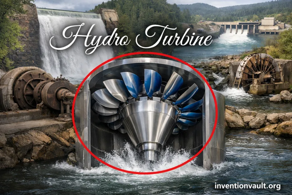
| Invention | Hydro Turbine (also called water turbine or hydropower turbine) |
| Primary Purpose | Convert the energy of moving or falling water into rotational mechanical power for a generator or industrial drive. |
| Core Principle | Water transfers momentum and pressure to a rotating runner; power scales with head, flow, and efficiency. |
| Main Families | Impulse turbines (jet-driven) and reaction turbines (pressure + velocity), plus kinetic (free-flow) systems. |
| Common Designs | Francis, Kaplan/Propeller, Pelton, Cross-Flow, Bulb/Tube/Straflo, and pump-turbines for pumped storage. |
| What Determines the Type | Mostly available head and site flow, then constraints like setting depth, efficiency targets, and civil layout. |
| Typical Peak Performance | Well-designed large units can reach very high efficiencies at their best operating point, often above 90%. |
| Typical Materials | High-strength steels (often stainless in wetted zones), engineered coatings, and precision-machined blade surfaces to manage erosion and cavitation. |
| Testing and Standards | Performance guarantees are commonly verified with model acceptance tests aligned with IEC 60193 (turbines, storage pumps, pump-turbines). |
| Why It Matters | Hydro turbines are the prime movers behind many hydropower plants, from large dams to compact run-of-river installations. |
A hydro turbine is a precision machine built to do one job exceptionally well: take water’s available energy and turn it into steady rotation. That rotation can drive a generator, a pump, or industrial equipment. The engineering looks calm on the surface—curved blades, smooth passages, polished metal—but inside, the design is all about controlling flow, pressure, and momentum so the runner extracts as much useful work as physics allows.
- What a Hydro Turbine Is
- Key Terms Used With Hydro Turbines
- How a Hydro Turbine Makes Power
- Hydraulic Inputs
- Mechanical Outputs
- Main Parts and What They Do
- Hydro Turbine Families
- Impulse Turbines
- Reaction Turbines
- Kinetic and Free-Flow Turbines
- Common Turbine Designs and Where They Fit
- Efficiency, Control, and Operating Range
- What Operators Measure
- Engineering Constraints That Shape the Design
- Testing, Guarantees, and Standards
- A Short History of the Modern Water Turbine
- Where Hydro Turbines Are Used Today
- Environmental and Safety Notes
- References Used for This Article
What a Hydro Turbine Is
In simple terms, a hydro turbine is a water-driven rotary engine. Water enters the turbine with a certain head (available energy per unit weight) and flow rate (volume per second). As water passes through the machine, part of that energy becomes torque on the shaft. The turbine is designed to leave the water with as little “wasted” swirl and speed as practical.
Key Terms Used With Hydro Turbines
- Head: The usable energy level difference driving the turbine (often expressed as net head after losses).
- Flow: How much water passes through per second; it strongly shapes runner size and passage geometry.
- Runner: The rotating part with blades or buckets that captures energy.
- Wicket gates: Adjustable guide vanes that regulate flow and set the entry angle into the runner.
- Draft tube: A diffuser used on many reaction turbines to recover pressure and reduce exit losses.
- Cavitation: Local boiling and bubble collapse that can pit metal surfaces; designs aim to keep pressure safely above critical zones.
How a Hydro Turbine Makes Power
Hydro turbines sit at the intersection of hydraulics and rotating machinery. The usable shaft power is commonly described by the relationship P ≈ ρ·g·Q·H·η, where Q is flow, H is net head, and η captures losses across the turbine and connected equipment. That compact expression hides a deep reality: performance depends on blade angles, surface finish, leakage control, and how cleanly the machine guides water through its passages.
Hydraulic Inputs
- Net head available at the turbine inlet
- Flow variability across seasons and operating modes
- Water quality factors like sediment and debris
- Tailwater level effects on pressure recovery
Mechanical Outputs
- Torque delivered to the shaft
- Speed matched to generator requirements
- Stable operation across load changes with governing
- Low vibration and long bearing life
Main Parts and What They Do
A modern hydro turbine is a system, not just a runner. The flow path is engineered so water arrives at the blades at the right angle, transfers energy with minimal shock, and exits with controlled swirl and pressure recovery. Each component supports that goal while protecting reliability and safety.
- Intake and penstock: Deliver water with manageable losses; design targets stable flow and controlled pressure transients.
- Spiral (scroll) case: Wraps flow evenly around the runner to equalize distribution.
- Stay vanes and wicket gates: Provide structural support and fine control of flow rate and entry angle.
- Runner: The energy-extraction heart; blade geometry is tuned for the site’s head and flow pattern.
- Draft tube (reaction turbines): Expands flow area to recover pressure and reduce exit velocity loss.
- Shaft, bearings, seals: Keep alignment precise; sealing and lubrication choices protect efficiency and service life.
- Governor and controls: Coordinate gate movement (and blade pitch in some designs) for stable speed and power.
Hydro Turbine Families
Hydro turbines are commonly grouped by how water transfers energy to the runner. This classification matters because it determines the physical layout, the pressure environment around the runner, and which operating ranges remain efficient and stable.
Impulse Turbines
Impulse turbines use one or more high-speed jets that strike buckets in air at near-atmospheric pressure. They shine where head is high and flow is comparatively modest. The classic example is the Pelton design, built around a split bucket that turns the jet and extracts momentum efficiently.
Reaction Turbines
Reaction turbines operate with the runner fully immersed and develop power from pressure change as well as velocity. This family includes Francis (mixed-flow) and Kaplan/propeller (axial-flow) designs. Their casings, gates, and draft tubes form a controlled pressure system, making hydraulic shaping and sealing especially important.
Kinetic and Free-Flow Turbines
Kinetic turbines capture energy primarily from water’s flow velocity rather than a large elevation difference. They can be installed in rivers, channels, and some tidal settings, typically using existing flow paths instead of a full pressurized penstock.
Common Turbine Designs and Where They Fit
The “right” hydro turbine is the one that matches the site’s hydraulic signature and operating priorities. Some designs handle wide flow swings gracefully, others chase top efficiency in a narrower band. The table below summarizes the most widely used turbine types and the conditions they typically serve.
| Turbine Type | Best-Fit Site Conditions | What It Is Known For |
|---|---|---|
| Pelton | Very high head, low-to-moderate flow | Jet-driven buckets with strong efficiency in high-head terrain; simple draft-tube requirements. |
| Cross-Flow | Low-to-medium head, steady to variable flow | Water passes through the runner twice; valued for robust operation and practical small-hydro layouts. |
| Francis | Medium to high head with broad applicability | Mixed-flow reaction design; widely used with excellent peak performance and mature engineering practice. |
| Kaplan / Propeller | Low head, high flow | Axial-flow runners; adjustable pitch in Kaplan units supports wide operating range. |
| Bulb / Tube / Straflo | Low head in compact waterways and constrained civil layouts | Packaging variations of propeller-family turbines that integrate the generator and flow passage efficiently. |
| Pump-Turbine (reversible) | Pumped storage plants with generation and pumping modes | A reversible machine (often Francis-based) that generates by day and pumps water back when needed. |
| Archimedes Screw (low-speed) | Very low head with debris-tolerant needs | Slow rotation and open geometry; often chosen where gentle flow handling and practical maintenance matter. |
Efficiency, Control, and Operating Range
Hydro turbines are celebrated for efficiency, but that efficiency lives on a curve, not a single number. Each runner has a “best point” where flow angles and pressure distribution align, and a surrounding envelope where performance remains strong. Designs with adjustable elements—like Kaplan blade pitch and wicket gate position—can keep the machine near its sweet spot as the river or reservoir conditions change.
What Operators Measure
- Net head at the machine, not just reservoir level
- Discharge through the turbine and gate position
- Efficiency trends across operating points (often visualized as a “hill chart” in engineering practice)
- Vibration and bearing temperatures as early reliability indicators
- Pressure fluctuations tied to draft tube behavior and transient events
Engineering Constraints That Shape the Design
The most impressive hydro turbines are defined by restraint: blade angles set to avoid flow separation, seal clearances balanced between leakage and rubbing risk, and pressure profiles managed so metal stays healthy over decades. The challenges below are routine in real projects, and they explain why turbine geometry is so site-specific.
- Cavitation risk: Local low pressure can damage runner surfaces; designers use geometry, materials, and operating limits to reduce exposure.
- Sediment erosion: Abrasive particles can wear leading edges and passages; coatings and material selection become critical.
- Debris and ice: Intakes, trash racks, and passage design protect the runner while keeping hydraulic losses controlled.
- Transient pressures: Gate movements and sudden load changes create pressure waves; layouts and controls must keep stresses within safe margins.
- Grid and generator coupling: Speed, inertia, and governing behavior must match electrical requirements for stable operation.
Testing, Guarantees, and Standards
Large hydro turbines are commonly validated through scale modeling and acceptance testing. Model tests allow engineers to compare runner variants, refine flow passages, and predict prototype performance with controlled measurements. International standards such as IEC 60193 define how model acceptance tests are arranged and how hydraulic performance guarantees are assessed for turbines and pump-turbines.
A Short History of the Modern Water Turbine
Water wheels powered human industry for centuries, but the modern turbine arrived when engineers learned to guide water through carefully shaped passages and measure performance with scientific rigor. The result was a family of machines that scale from compact installations to massive generating units.
- 1827: Benoît Fourneyron builds a notable early hydraulic turbine prototype, demonstrating the leap from traditional wheels to engineered turbines.
- Mid-19th century: The Francis reaction turbine emerges as a practical standard for broad head ranges and high output.
- Late 19th century: Pelton impulse technology proves its value where high head is available and jet control is practical.
- 1910s: Viktor Kaplan develops the adjustable-blade propeller concept, enabling strong efficiency under low-head, high-flow conditions.
- 20th century onward: Reversible pump-turbines support pumped storage by operating as both turbine and pump, extending the role of hydro machinery beyond direct river generation.
Where Hydro Turbines Are Used Today
Hydro turbines are used wherever water can deliver dependable energy to a rotating shaft. The installation style changes—dam, diversion, canal, powerhouse cavern—but the essentials stay the same: control the flow, protect the machine, and keep operation stable across real-world variability.
- Conventional hydropower plants: Pressurized penstocks drive Francis or propeller-family units, producing steady electricity.
- Run-of-river systems: Lower head and seasonal flow shifts often favor designs that remain efficient across a broad operating band.
- Pumped storage facilities: pump-turbines switch between generating and pumping to support flexible system operation.
- Small and micro hydro: Compact turbines and practical civil works deliver local power where appropriate water resources exist.
- In-channel and free-flow applications: kinetic turbines can operate within existing flow paths under the right engineering and safety constraints.
Environmental and Safety Notes
Modern hydropower projects commonly integrate turbine choices with broader site design so water, machinery, and operations remain compatible. Practical approaches include debris management at intakes, sediment-aware operating strategies, and site-specific measures that support aquatic movement while maintaining reliable generation. Inside the plant, safety focuses on controlled access, lockout procedures, and continuous monitoring of vibration and temperatures to protect people and equipment.
References Used for This Article
- U.S. Department of Energy — Types of Hydropower Turbines: Authoritative overview of turbine families, components, and selection drivers.
- U.S. Geological Survey — Hydroelectric Power: How it Works: Clear explanation of how turbines and generators produce electricity from water.
- U.S. Energy Information Administration — Hydropower Explained: Concise description of hydropower plant layouts and turbine role in generation.
- International Electrotechnical Commission — IEC 60193:2019: Standard describing arrangements for model acceptance tests and hydraulic performance guarantees.
- Encyclopaedia Britannica — Benoît Fourneyron: Reliable biographical reference for early turbine development milestones.
- Science Museum Group Collection — Fourneyron Turbine, 1837: Museum documentation of a Fourneyron-style turbine and its early adoption.
- U.S. National Park Service — James B. Francis: Historical profile of Francis and his contributions to turbine engineering practice.
- ASME — Pelton Waterwheel Collection: Engineering-history landmark describing the Pelton wheel and its significance.
- Science Museum Group Collection — Pelton Water Turbine: Museum entry noting key facts about Pelton turbine development and use.
- MDPI Energies — A Brief History of the Kaplan Turbine Invention: Scholarly review covering Kaplan’s development path and early patent timeframe.