Fiber Optic Cable Details
| Technology Name | Fiber Optic Cable (optical fiber) |
| What It Does | Moves information as light pulses through a glass (or plastic) fiber. |
| Core Physical Idea | Total internal reflection keeps light trapped in the core by reflecting at the core–cladding boundary. |
| Modern Breakthrough | Mid-1960s work showed glass could reach < 20 dB/km loss targets for practical communication. |
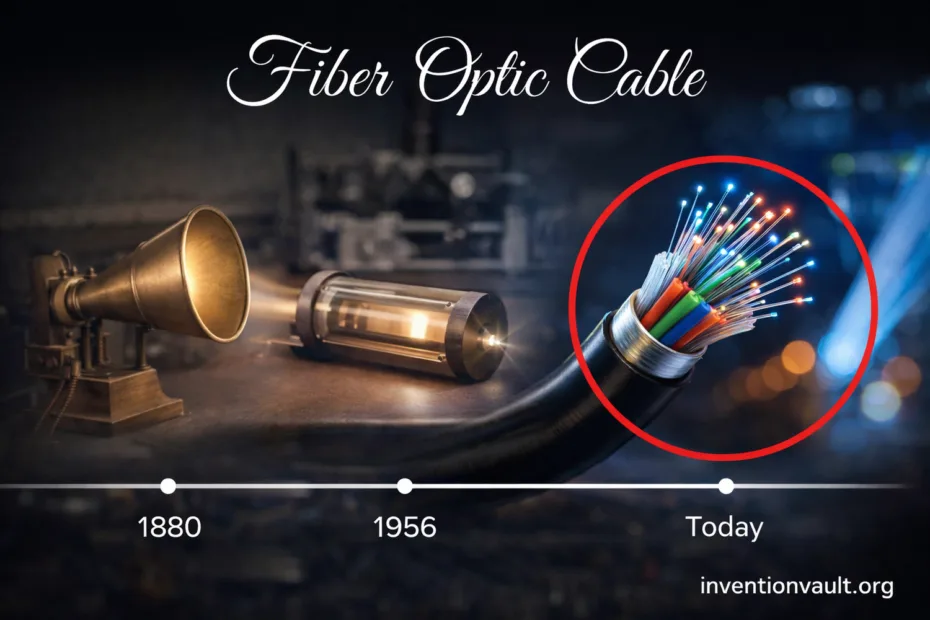
| First Low-Loss Fiber (1970) | Corning researchers produced fiber around 16–17 dB/km loss, a step that made long-distance fiber systems realistic. |
| Early City Deployment (1977) | Early optical telephone systems were installed in downtown Chicago in 1977. |
| First Transoceanic Milestone (1988) | TAT-8 entered service on December 14, 1988, widely cited as the first transatlantic fiber-optic submarine cable. |
| Typical Materials | Very pure silica glass core and cladding; protective coatings and jackets for handling and environment. |
| Common Dimensions | Cladding is usually 125 μm. Single-mode core is about 8–10 μm; multi-mode cores are often 50 μm or 62.5 μm. |
| Key Wavelength Bands | 850 nm, 1310 nm, and 1550 nm are widely used “windows” because glass is relatively transparent there. |
| Typical Loss Today | Modern single-mode fibers can be around 0.2 dB/km near 1550 nm (values vary by fiber type and installation). |
| Common Connector Families | LC, SC, ST, and multi-fiber MPO/MTP. |
| Splice Methods | Fusion splicing (lowest loss, permanent) and mechanical splicing (faster, higher loss). |
| Why It Matters | High bandwidth, low interference, and long distances make fiber the backbone of modern connectivity. |
| Main Engineering Limits | Attenuation, dispersion, bend sensitivity, connector cleanliness, and careful installation. |
A fiber optic cable looks simple from the outside, yet inside it is a carefully engineered path for light that carries data at remarkable scale. It is not “internet-in-a-tube.” It is a precision waveguide designed to protect a fragile glass thread while keeping signals clean, fast, and stable.
- Fiber Optic Cable Details
- Key Milestones
- How Light Becomes Data
- Transmitter Side
- Receiver Side
- Core Parts Inside a Fiber
- Why Total Internal Reflection Works
- Fiber Types and Modes
- Optical Windows and Common Wavelengths
- Cable Designs and Sub-Types
- A Practical Example: Why Cable Geometry Matters
- Connectors, Splices, and Cleanliness
- Attenuation and Dispersion
- WDM and DWDM: Many Channels on One Strand
- What Makes DWDM Powerful
- Where Fiber Optic Cable Is Used
- Testing, Reliability, and Everyday Care
- Safe Handling Notes
- Compact Glossary
- References Used for This Article
Key Milestones
- 1966 — Research highlighted that ultra-pure glass could hit a practical loss target (below 20 dB/km) for communication.
- 1970 — Low-loss glass fiber demonstrated around 16–17 dB/km, unlocking realistic long links.
- 1977 — Early optical telephone systems appeared in city infrastructure, proving the concept outside labs.
- 1988 — TAT-8 entered service as a landmark transatlantic fiber-optic submarine system.
How Light Becomes Data
Fiber links move digital signals by turning electrical bits into optical pulses at a transmitter, guiding those pulses through optical fiber, and converting them back to electricity at a receiver. The trick is that a single strand can carry many streams at once, using modulation (how the light is “wiggled”) and often multiple wavelengths (different colors of infrared light).
Receiver Side
- A photodiode turns light back into an electrical signal.
- Signal processing cleans up noise and timing errors.
- Network gear rebuilds the original data stream for switching and routing.
Light does not travel “as-is.” A fiber system cares about signal shape, timing jitter, and how pulses spread out over distance due to dispersion. That is why transceivers (like SFP modules) and amplifiers exist: they keep capacity high while preserving a clean eye pattern at the receiver.
Core Parts Inside a Fiber
Every optical fiber has two essential layers: the core (where most light energy travels) and the cladding (a slightly lower refractive index glass that enables total internal reflection). Around that glass sit protective layers: a soft coating, strength members, and an outer jacket that lets installers handle something that would otherwise snap like a thin noodle.
Why Total Internal Reflection Works
When light in the core hits the boundary at a steep enough angle, it reflects back in, instead of escaping. This “trap” is not a trick; it is a property of refractive index and geometry. The result is a guided path where loss is low and bandwidth stays high across long distances.
Fiber Types and Modes
Not all fibers behave the same. The “type” is mainly about how many modes (paths) of light can propagate. Fewer modes means less pulse spreading, which means cleaner signals at long range. More modes can be easier to couple light into, which is handy for shorter runs. That tradeoff is a big reason both single-mode and multi-mode exist.
| Fiber Category | Typical Core Size | Strength | Common Fit |
|---|---|---|---|
| Single-Mode (SMF) | About 8–10 μm | Very long distances, high capacity, low dispersion | Backbone, metro rings, long links, DWDM systems |
| Multi-Mode (MMF) | 50 μm or 62.5 μm | Easier coupling, cost-effective optics for short runs | Data centers, buildings, campus links |
Within multi-mode, you’ll also see step-index and graded-index designs. Graded-index fiber smooths out travel time differences between modes, reducing modal dispersion. In practice, this means a better chance of clean high-speed links across typical building distances. It is a subtle design choice with a real, measurable payoff.
Optical Windows and Common Wavelengths
Glass is not equally transparent at all wavelengths. Fiber systems cluster around 850 nm, 1310 nm, and 1550 nm because they sit in “windows” where attenuation is low enough to be useful. The choice affects reach, amplifier options, and dispersion behavior, so it is not just a random spec line.
| Window | Typical Use | What It Optimizes |
|---|---|---|
| 850 nm | Mostly multi-mode links | Short-range optics and economical components |
| 1310 nm | Single-mode access and metro | Balanced loss and dispersion behavior |
| 1550 nm | Long-haul and DWDM | Lowest loss region and strong amplifier ecosystem |
When engineers talk about “distance,” they rarely mean the cable length alone. They mean a loss budget: total connector loss, splice loss, fiber attenuation per kilometer, and safe margin. A clean connector endface can be the difference between a stable link and a stubborn intermittent fault. That part is realy easy to underestimate.
Cable Designs and Sub-Types
“Fiber optic cable” can mean many constructions built around the same glass. The sub-types exist because installations demand different things: flexibility, crush resistance, water blocking, density, or fast termination. The fiber strand is tiny; the cable engineering is what makes it deployable in the real world with reliable performance.
- Loose-Tube Cable: Fibers sit in a tube with room to move, helping with temperature changes and outdoor use; often includes water-blocking elements.
- Tight-Buffered Cable: Coating is tighter for easier handling and termination; common indoors.
- Ribbon Fiber: Many fibers aligned in flat ribbons to pack high counts and speed up mass splicing.
- Armored Cable: Added metal protection for harsh environments and rodent resistance.
- Aerial Cable: Built to hang on poles with strength members and weather tolerance.
- Submarine Cable: Layered protection and repeaters/amplifiers designed for long, stable underwater operation.
A Practical Example: Why Cable Geometry Matters
A fiber can lose light if it is bent too tightly. Designers fight this with bend-insensitive fibers, better coatings, and cable structures that enforce a safer bend radius. A small physical choice leads to better installation tolerance and fewer mystery drops in link power.
Connectors, Splices, and Cleanliness
Most fiber problems are not “the glass went bad.” They are connection problems: dust, oil films, scratches, poor mating pressure, or micro-gaps. A connector endface is tiny, and small contamination can block the core area. That is why technicians treat inspection and cleaning as first-class engineering tasks, not a last-minute habit.
| Joining Method | What It Is | Typical Strength | Where It Shines |
|---|---|---|---|
| Fusion Splice | Glass ends aligned and fused with heat | Very low loss, durable | Permanent outdoor/long links, high fiber counts |
| Mechanical Splice | Alignment sleeve and index gel clamp fibers | Faster, typically higher loss | Repairs, temporary work, quick field restoration |
| Connector Mate | Removable interface (LC/SC/MPO, etc.) | Convenient, depends on cleanliness | Patch panels, equipment ports, modular builds |
Multi-fiber connectors like MPO/MTP push density higher, but they raise the stakes on polarity, endface quality, and insertion loss. A clean, well-verified cable plant is what turns “high density” into high uptime, instead of a maze of intermittent errors.
Attenuation and Dispersion
Two big physics realities shape every fiber system: attenuation (signal loss) and dispersion (pulse spreading). Attenuation decides how far light can go before it becomes too faint. Dispersion decides how fast the bits can be before they smear into each other. Good design respects both, with optics matched to the fiber type and distance.
| Effect | What You See | Typical Fix |
|---|---|---|
| Attenuation | Receiver power drops below threshold | Better loss budget, fewer connectors, higher power optics, amplifiers (where appropriate) |
| Chromatic Dispersion | Pulses spread with wavelength differences | Use suitable wavelengths, dispersion compensation, coherent optics for high rates |
| Modal Dispersion | Multi-mode pulses smear over distance | Graded-index MMF, shorter runs, or switch to single-mode |
Engineers often describe fiber capacity as “near limitless,” but physics still sets boundaries. The good news is that clever techniques keep moving those boundaries: better glass, better lasers, better modulation formats, and more wavelengths through multiplexing. Fiber’s strength is that improvements tend to stack, year after year.
WDM and DWDM: Many Channels on One Strand
A single fiber can carry multiple wavelengths at once, each acting like a separate lane on the same highway. This is wavelength-division multiplexing (WDM). Dense versions, DWDM, pack many more wavelengths into the same fiber, allowing enormous aggregate throughput. This is a major reason fiber scales so well without constantly pulling new cables.
What Makes DWDM Powerful
- Capacity growth without new trenches or ducts.
- Service separation by wavelength, useful for large networks.
- Pairs naturally with optical amplifiers in long routes.
- Turns a single strand into a multi-terabit transport resource (depending on equipment and design).
Where Fiber Optic Cable Is Used
You can think of modern connectivity as layered. Fiber shows up in almost every layer because it offers high bandwidth with stable performance over distance. The same underlying technology supports short indoor patching and massive long-haul routes; the difference is the design of the cable plant and the optics at each end.
- Backbone and Long-Haul: High-capacity transport between cities and regions, often using single-mode and WDM.
- Metro Networks: Rings that connect neighborhoods, data centers, and network hubs with strong redundancy.
- Access and FTTH: Fiber closer to homes and buildings for fast, consistent service.
- Data Centers: Dense patching and high-speed links using MMF and SMF depending on distance and architecture.
Testing, Reliability, and Everyday Care
Fiber is durable when protected, yet it demands respect at the interfaces. A healthy fiber plant is usually verified with power measurements and distance-to-fault tools like OTDR, which can reveal splice loss, reflections, and unexpected bends. These tests are not just for troubleshooting; they create a baseline so future changes are easy to spot.
Safe Handling Notes
- Never look into the end of a live fiber. Many systems use infrared light you can’t see, yet it can still harm eyes.
- Keep endfaces clean; dust is the quiet enemy of signal quality.
- Respect bend radius. A gentle route preserves optical power and long-term stability.
Compact Glossary
| Term | Meaning |
|---|---|
| Attenuation | How much signal power is lost as light travels through fiber, often expressed in dB/km. |
| Dispersion | Pulses spread in time, which can blur bits at high rates; a major limit for speed over distance. |
| Mode | A stable path light can take inside a fiber; single-mode carries essentially one main mode for long reach. |
| WDM / DWDM | Multiple wavelengths on one fiber; DWDM packs many tightly spaced channels for high capacity. |
| OTDR | A test instrument that maps loss and reflections along a fiber to locate splices, bends, and faults. |
| Insertion Loss | Loss introduced by a connector, splice, or device; small numbers add up in a loss budget. |
References Used for This Article
- International Telecommunication Union (ITU) — G.652: Characteristics of a single-mode optical fibre and cable: Defines baseline single-mode fiber performance parameters used across telecom networks.
- The Nobel Prize — The Nobel Prize in Physics 2009 (Summary): Summarizes the recognized breakthrough that enabled practical optical-fiber communications.
- IEEE Engineering and Technology History Wiki (ETHW) — Fiber Optics: Provides a curated historical overview of early fiber-optics research and adoption.
- Corning Incorporated — Corning Discovers Low-Loss Fiber (1970): Documents the first low-loss fiber results that made long-distance links realistic.
- IEEE Milestones (ETHW) — World’s First Low-Loss Optical Fiber for Telecommunications (1970): Independently records the 1970 low-loss fiber milestone and its technical significance.
- Corning Incorporated — Fiber Gets Real with Single-Mode Fiber Development (Timeline): Notes early real-world telephone deployments, including the Chicago installation mentioned in the article.
- IEEE Milestones (ETHW) — Trans-Atlantic Telephone Fiber-Optic Submarine Cable (TAT-8), 1988: Confirms the TAT-8 in-service date and why it mattered for transoceanic communications.
- University College London (UCL) — Fibre optic connectors – a different “view” (PDF): Explains common connector families and the standards ecosystem supporting interoperability.