| Detail | Information |
|---|---|
| Invention Name | Electric Generator |
| Core Scientific Basis | Electromagnetic induction: electrical voltage is produced when a conductor experiences a changing magnetic environment (by motion, field change, or both). |
| Early Breakthrough (Demonstration) | 1831: Michael Faraday’s unipolar (homopolar) disk generator, often called the “Faraday disk,” showed continuous current from rotation in a magnetic field. |
| Early Machine Form (Magneto) | ca. 1832: Hippolyte Pixii’s magneto-electric machine produced alternating current that could be rectified to pulsed direct current using an early commutator concept. |
| Key Industrial Step | 1860s: Self-excitation (using electromagnets energized by the machine itself) enabled stronger fields and practical scaling. |
| Practical DC Generator Era | Late 19th century: design advances (armatures, commutation, field systems) made DC dynamos reliable for lighting and industry. |
| Modern Main Output Forms | AC alternators (grid power) and DC generators (specialized industrial uses); many systems use rectification to obtain DC. |
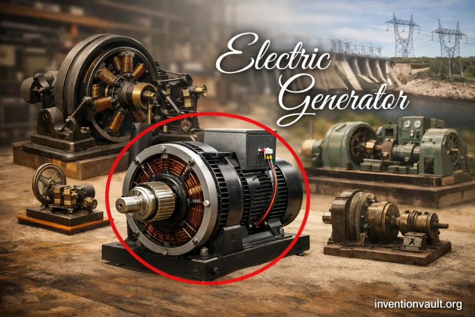
| Essential Hardware | Rotor, stator, field system (permanent magnets or electromagnets), windings, and either slip rings (AC) or a commutator (traditional DC dynamos). |
| What It Converts | Mechanical energy → electrical energy through controlled motion and magnetic fields. |
| Where It Shows Up | Power stations, turbines, engines, wind systems, portable generators, and many industrial machines that need reliable electricity. |
Electric generators sit at the center of modern technology because they turn motion into usable electricity. The invention story is not a single moment so much as a sequence: a new physical effect is discovered, a first working device proves it, then designs mature until they become dependable machines. When historians say “the invention of the electric generator,” they usually mean this whole chain—from induction experiments to the first practical dynamos and today’s alternators.
- What an Electric Generator Is
- Origins of Electromagnetic Induction
- Faraday’s Disk and Early Proof
- Pixii’s Magneto-Electric Machine
- From Demonstrations to Practical Dynamos
- A Useful Way to Think About the Evolution
- How an Electric Generator Works
- Main Parts
- Energy Flow
- Generator Types and Their Subfamilies
- DC Dynamos: Why Commutation Was a Big Deal
- Alternators: The Dominant Modern Form
- Key Performance Measures
- Materials and Engineering Choices That Shaped Reliability
- How Generators Became a Platform Technology
- Common Questions About the Invention
- References Used for This Article
What an Electric Generator Is
Definition: An electric generator is a machine that produces electrical power by moving a conductor through a magnetic field, or by changing the magnetic field around a conductor, so that voltage is induced.
- It is not a battery. A battery stores chemical energy; a generator creates electricity continuously while motion is supplied.
- It is not tied to one shape. Rotation is common, yet linear generators exist where parts move back and forth.
- It comes in families. “Dynamo” often refers to traditional DC machines; “alternator” is typically AC.
Origins of Electromagnetic Induction
The generator begins with a deceptively simple idea: magnetic effects and electric effects are linked. Once experimenters learned that changing magnetism can induce voltage, the door opened to machines that make electricity on demand. In 1831, Faraday’s experiments established a clear path from magnetic change to induced voltage.
Faraday’s Disk and Early Proof
Faraday’s rotating copper disk generator is famous because it produces current in a continuous way rather than in brief pulses. The geometry is clean: a conductor rotates in a magnetic field, charges experience a force, and an electrical potential appears between the center and the rim. That principle is still taught today because it highlights the motion-driven side of induction.
Pixii’s Magneto-Electric Machine
Very soon, instrument makers began building machines aimed at generating stronger effects. Pixii’s early magneto-electric design used a rotating magnet and coils to produce alternating current. With a commutating mechanism, its output could be redirected into a one-direction pulsing current—an important step toward practical DC generation.
From Demonstrations to Practical Dynamos
Early generators proved induction, yet real-world electricity demanded more: steadier output, stronger magnetic fields, and designs that could run for long periods with predictable performance. Several innovations converged—improved armatures, better commutation, and the shift from permanent magnets to electromagnetic field systems that could be intensified and controlled.
| Period | Milestone | Why It Mattered |
|---|---|---|
| 1831 | Faraday’s unipolar disk generator | Proved continuous current from rotation in a magnetic field. |
| ca. 1832 | Pixii’s magneto-electric generator | Early machine approach to producing current; introduced rectification ideas via commutation. |
| 1860–1863 | Pacinotti’s ring armature | Smoothed DC output by distributing coils around a ring, supporting steadier performance. |
| 1866 | Self-excited dynamo principle | Allowed generators to build stronger fields using their own output, enabling practical scaling. |
| 1870s | Industrial dynamos (refined armatures, commutation, manufacturing) | Reliable machines made electricity a dependable utility for lighting and industry. |
| Late 19th–20th century | High-speed alternators and turbine-driven generators | Made large-scale AC generation efficient for transmission and broad distribution. |
A Useful Way to Think About the Evolution
- Phase 1: Prove induction can create a measurable voltage.
- Phase 2: Build machines that generate more than laboratory effects.
- Phase 3: Improve field strength, armature geometry, and current collection so the output becomes stable and scalable.
How an Electric Generator Works
At its heart, a generator arranges conductors and magnetic fields so that charge carriers are pushed into motion. The induced voltage depends on how quickly magnetic conditions change across the windings. In compact form, Faraday’s principle is often expressed as emf proportional to the rate of change of magnetic flux.
emf = - N · (dΦ/dt)Main Parts
- Stator: the stationary structure; often carries the main magnetic field or windings.
- Rotor: the rotating element; carries windings or magnetic poles depending on design.
- Field system: permanent magnets or electromagnets that establish the magnetic field.
- Armature windings: conductors where voltage is induced.
- Slip rings (AC) or commutator (traditional DC): the interface that delivers power from rotating parts.
- Regulation and protection: controls that keep output within intended limits.
Energy Flow
Prime mover (engine / turbine / wind)
              │
              ▼
         Rotating shaft
              │
              ▼
   Magnetic field + conductors arranged
              │
              ▼
     Induced voltage in windings
              │
              ▼
  Output conditioned (AC or rectified DC)
In modern systems, the machine is paired with electronics that shape voltage, control frequency, and improve stability—without changing the underlying induction mechanism.
Generator Types and Their Subfamilies
“Electric generator” is an umbrella term. The differences are usually about the type of current, how the field is produced, and how output is collected. The table below summarizes the main families without getting lost in brand-specific designs.
| Family | Typical Output | Signature Hardware | Where It Commonly Appears |
|---|---|---|---|
| DC Generator (Dynamo) | Direct current (often smoothed) | Commutator and brushes; armature designed for manageable commutation | Specialized industrial uses, legacy systems, educational and historical machines |
| AC Generator (Alternator) | Alternating current | Slip rings; rotating field and stationary armature are common in large units | Power grids, power stations, vehicle alternators, large standby units |
| Permanent Magnet Generator | AC or rectified DC | Permanent magnets for the field; simpler excitation | Small wind systems, compact devices, portable applications |
| Induction Generator | AC (grid-coupled in many cases) | Rotor resembles an induction motor; needs suitable excitation conditions | Wind generation and systems where grid interaction is part of the design |
| Homopolar (Unipolar) Generator | Low-voltage, high-current DC potential | Conducting disk or cylinder in a steady field; simple geometry | Special research and niche high-current applications |
| Linear Generator | AC or rectified DC | Back-and-forth motion instead of rotation | Wave-energy concepts, specialized mechanical systems |
DC Dynamos: Why Commutation Was a Big Deal
Early machines could produce changing voltages, yet delivering a useful one-direction output required careful current collection. The commutator’s role is to switch coil connections at the right moment so the external circuit sees consistent polarity. That single component shaped much of 19th-century generator engineering: brush materials, armature design, and the quest for smoother output.
Alternators: The Dominant Modern Form
Alternators typically produce AC directly, which can be transformed efficiently for distribution and then converted when DC is needed. Their architecture also reduces the challenges of mechanical switching that traditional commutators face, especially at higher speeds and larger power levels.
Key Performance Measures
Generators are specified in a language that connects physics to real systems: voltage, current, power, frequency, and speed. These terms make it possible to compare designs across eras—from early hand-cranked machines to modern turbine-driven units.
| Measure | Unit | What It Tells You |
|---|---|---|
| Voltage | V | Electrical “pressure” that drives current through a load. |
| Current | A | Flow rate of electric charge delivered to the circuit. |
| Power | W, kW, MW | How much energy per second the generator can supply. |
| Frequency (AC) | Hz | How fast the AC waveform repeats; tied to rotation and pole count. |
| Speed | rpm | Mechanical rotation rate; influences voltage and frequency. |
| Efficiency | % | How much mechanical input becomes electrical output after losses. |
Materials and Engineering Choices That Shaped Reliability
Once generators moved beyond demonstrations, reliability became the real frontier. Designers refined magnetic circuits, windings, and insulation so that machines could operate steadily. Many improvements look subtle on the outside, yet they define modern performance.
- Laminated steel cores: reduce energy lost to eddy currents in changing magnetic fields.
- Copper windings: provide low resistance for efficient current flow, especially in high-power machines.
- Insulation systems: separate conductors safely while tolerating heat and mechanical vibration.
- Cooling and airflow: control temperature so electrical properties remain stable over long runs.
- Precision bearings and alignment: keep rotating parts smooth, protecting both efficiency and lifespan.
How Generators Became a Platform Technology
As generator output became more stable and scalable, it stopped being a laboratory curiosity and became a platform for other inventions. Lighting systems, industrial motors, and later large distribution networks all depended on dependable generation. The generator also created a feedback loop in engineering: better generators enabled more demanding electrical systems, and those systems pushed generator design to improve even further.
Common Questions About the Invention
Was there one inventor? The first demonstrations are strongly associated with Faraday, yet practical generators emerged through multiple contributors and design steps over decades.
Why do some sources say “dynamo” and others say “generator”? “Generator” is the broad category. “Dynamo” often refers to traditional DC machines that rely on commutation, while “alternator” usually refers to AC machines.
Did generators come before electric motors? They developed in parallel, and the deeper insight is that many designs are reversible: a motor and a generator can share core architecture, with energy flowing in opposite directions.
References Used for This Article
- Museo Galileo — Magneto-electric machine by Pixii: Museum entry describing an early magneto-electric generator and its operation.
- Engineering and Technology History Wiki (ETHW) — First Studies on Ring Armature for Direct-Current Dynamos, 1860-1863: IEEE milestone page summarizing Pacinotti’s ring-armature dynamo work.
- The Norwegian Museum of Science and Technology — The energy exhibition – Historical part: Museum text noting the 1866 self-magnetizing dynamo breakthrough associated with Siemens.
- National MagLab — Gramme Dynamo – 1871: Overview of the Gramme dynamo and why it became a landmark industrial generator.
- Encyclopaedia Britannica — Faraday’s law of induction: Definition and formula-level explanation of induction used to frame generator operation.
- Encyclopaedia Britannica — self-excited generator: Concise reference on self-excitation and its role in stronger generator fields.
- Joseph Henry Project (Princeton) — Faraday’s Flux Rule: Educational discussion of induction and unipolar generator behavior.
- PhET Interactive Simulations (University of Colorado Boulder) — Generator – Faraday’s Law | Induction | Electricity: Interactive simulation page illustrating how changing magnetic conditions induce voltage.